Author Topic: [Restauration] Crazy Kong fase 1  (Read 55454 times)

level42

  • ArcadeLifeStyler'
  • ***
  • Posts: 13555
  • Ridderkerk, arcade capital of Europe !
    • View Profile
    • Arcade 42
Re: [Restauration] Crazy Kong fase 1
« Reply #45 on: October 24, 2010, 12:29:55 PM »
You say you are measuring on pins on the board. WHAT pins ? Near the connector ??

You should measure about "half-way" the board. Maybe there are some dedicated +5V test points there (although I doubt it) but else just pick a TTL IC and measure it's supply voltage pin (usually the one that is opposite pin 1, so on the other side of the body).
There should be plenty of GND points (large area's/tracks) to find around the same spot, or else also measure that on the IC itself, ususally on TTL IC's the GND pin is diagonally across the +5V supply pin....

See here for some drawings: http://www.kpsec.freeuk.com/components/74series.htm

If you have like 4,6V on the beginning of the board, imagine what it will be on the end....

TTL tolerance os only about 0,25V, so it has to be between 4.75V and 5.25 ACROSS the board...
You already start too low so, yes pump it up (in very slow steps).

You could just as well have used the 100 Ohms pot by the way, as long as you kept it around the initial value of the original resistor.

I am jealous of your desoldering station by the way ! :)

Oh....and REMOVE your rings before working on electronics or electricity !!!!!! Rings are great as contacts to give you a nice shock OR even "only" short circuits by accident !

Etienne MacGyver

  • ArcadeLifeStyler'
  • ***
  • Posts: 7611
  • The Netherlands
    • View Profile
Re: [Restauration] Crazy Kong fase 1
« Reply #46 on: October 24, 2010, 01:47:46 PM »
Oh....and REMOVE your rings before working on electronics or electricity !!!!!! Rings are great as contacts to give you a nice shock OR even "only" short circuits by accident !

Good tip, havent thought about that  :oops:
Silver is even a better conductor than cupper , so i'll keep that in mind!

I measured the "edgeconnector" from the board, the blank section just after the connector before it goes into the circuit, i hope you know what i mean  :D

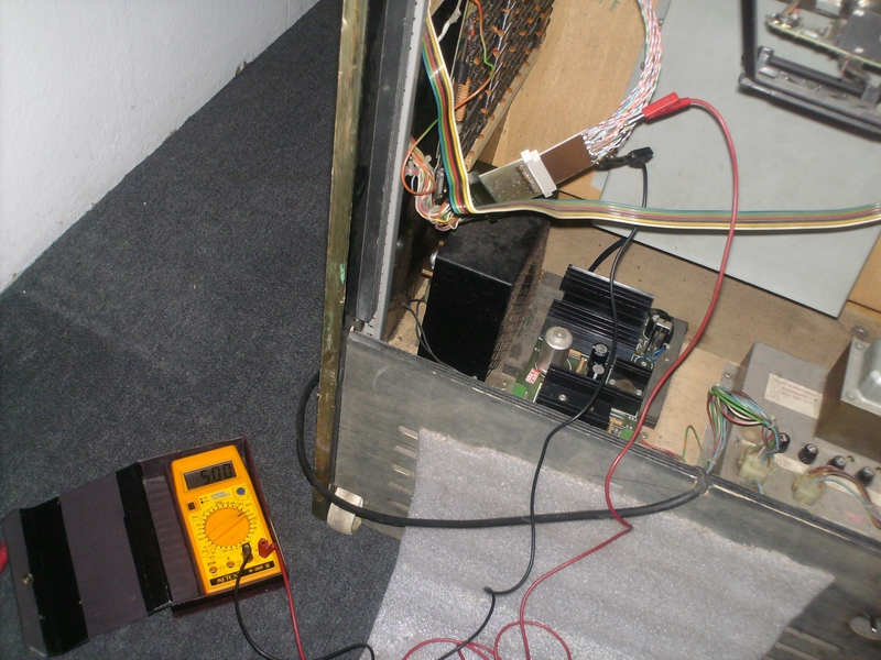
anyway, i just went to test it at my mothers place (where the cab lives..)

I connected first the FCK-01 board since that was working, and i checked if it was working
that part was ok, then i connected the FCK-00 board and started to increase the voltage
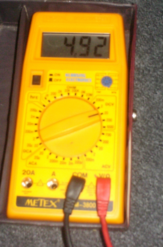
at the end of the pod i have a maximum voltage of .......


I reboot, and it looks alot more promissing than before.
it started, and i could play..  (like before...)

Again at level 3 it crashes and i never had a good boot after that like the first time

So i think the voltage is still too low like you explain andre, imagine in the middle of the circuit..

So for now i put the original board with the graphic issue, since its possible to regulate the power , i adjusted thatone exactly to 5 Volts.


The graphic issue is still there, but at least it got the proper voltage now

i measured the pot in the "maximum position" and i see that it has the high value of resistence, so it means the more resistence in the place of the resistor, the higher the voltage, i can not go higher because the pot is at his max of 50 ohms.

Gives me a theory...

If 50 ohms give me almost 5 volts, Can i replace it with one of 100 ohms and give the board more than the 50 ohms resistence so the voltage will be 5 volts without damaging the powersupply ?

another nice thing is that they still carry 100 ohms in the "onboard" variant, so the nice extention i made is no longer nessesary...

level42

  • ArcadeLifeStyler'
  • ***
  • Posts: 13555
  • Ridderkerk, arcade capital of Europe !
    • View Profile
    • Arcade 42
Re: [Restauration] Crazy Kong fase 1
« Reply #47 on: October 24, 2010, 10:26:24 PM »
Well.....this is the essential schematic with the included formula....


In your case, the pot is R2.
R1=R1

VoutIC is of course 5 Volt.


 Now, we don't know Ib so it's hard to know the figures.....

I think you'd be able to try the 100 Ohms pot...but be slow with increasing it's value !


level42

  • ArcadeLifeStyler'
  • ***
  • Posts: 13555
  • Ridderkerk, arcade capital of Europe !
    • View Profile
    • Arcade 42
Re: [Restauration] Crazy Kong fase 1
« Reply #49 on: October 25, 2010, 12:01:50 AM »
He's got a 50 Ohms in there now but it can't get the voltage high enough so that's why we are discussing the 100 Ohms...

Etienne MacGyver

  • ArcadeLifeStyler'
  • ***
  • Posts: 7611
  • The Netherlands
    • View Profile
Re: [Restauration] Crazy Kong fase 1
« Reply #50 on: October 25, 2010, 06:33:28 AM »
tanks flip but....

exactly Andre  8)

Etienne MacGyver

  • ArcadeLifeStyler'
  • ***
  • Posts: 7611
  • The Netherlands
    • View Profile
Re: [Restauration] Crazy Kong fase 1
« Reply #51 on: October 25, 2010, 12:13:29 PM »
I have decided to keep the first board in for now

after talking to belike, i found out that he was not bidding anymore on the board, so i took a gamble and i won this on ebay...


It looks in this picture that the green is missing from the RGB..., i hope its his monitor, and not the board..

Ully is so kind to forward it to the netherlands since the seller only ships in germany..

I will try that board, before i blow up my powersupply with wrong parts  ;D

The other two boards will visit Robinholland for investigation, its always good to have a spare  8)

ps. @ Robin, are you almost setup for the board investigation ?
« Last Edit: October 31, 2010, 10:41:07 AM by Etienne [NL] »

flip971

  • Member
  • **
  • Posts: 236
    • View Profile
    • Retrogame
Re: [Restauration] Crazy Kong fase 1
« Reply #52 on: October 26, 2010, 12:15:54 AM »
Just for completing the datas for the power supply.
I found a datasheet of the transistor TA78H05KC , here the link:http://img827.imageshack.us/img827/6548/datasheetua78h05kc.pdf
Some info on it can be usefull.

level42

  • ArcadeLifeStyler'
  • ***
  • Posts: 13555
  • Ridderkerk, arcade capital of Europe !
    • View Profile
    • Arcade 42
Re: [Restauration] Crazy Kong fase 1
« Reply #53 on: October 26, 2010, 12:57:56 AM »
The 78(H)05 is not a transistor. It's an analogue IC that is a fixed voltage regulator.

Simply put: You put unregulated DC in, and you get a very tight constant fixed voltage out. 78 means positive, 79 means negative voltage and 05 means 5 Volts in this case. So a 7924 puts out -24V.

They require the help of minimum two caps one on the input, one on the output. Sometimes a little more is used, but that is essentially it.

The "limit" of these range of regulators is that you can normally not adjust them. The trick with the pot and fixed resitor makes it possible to increase the voltage (to certain limits of course). But I think this is at the cost of some of the "tightness" of the singal.

It is pretty rare to see 78(H)05 (the H in this case means that it is high amps, so it is high power) in an arcade game for the MAIN +5V. Usually something else is used that is meant to be regulated from the start. Usually only the voltages that eat up relatively small amounts of power are created using 78xx or 79xx voltage regulators.

Etienne, you can try the 100 Ohms pot. If you really don't trust it, try to regulate it without the board connected first. Remember, a 100 Ohms pot runs from 0-100 Ohms. A 50 Ohms pot goes from 0-50 Ohms. So, as long as you set-up the 100 Ohms pot at the initial value (I think you mentioned 20 Ohms) and then increase it slowly (while measuring) you can see what happens.

Etienne MacGyver

  • ArcadeLifeStyler'
  • ***
  • Posts: 7611
  • The Netherlands
    • View Profile
Re: [Restauration] Crazy Kong fase 1
« Reply #54 on: October 26, 2010, 06:58:23 AM »
thanx for the input
i get your theory, it remebers me how we build a powersupply for the 3Meter Fm transmitter we used to play with..

i remember the 7812 IC that we used for that, but its true it looks like this:


I also remember that the component we use for more than 3 Amps was in a "case"  like the one in this cab , but that was a 3055 mostly..
that is a transistor, like flip means


i dont remember how we did all that.., it has been 20 years ago  :D

I need to find some time to check it out , this week is very busy...

level42

  • ArcadeLifeStyler'
  • ***
  • Posts: 13555
  • Ridderkerk, arcade capital of Europe !
    • View Profile
    • Arcade 42
Re: [Restauration] Crazy Kong fase 1
« Reply #55 on: October 26, 2010, 07:27:03 AM »
Yup, the first pic you show is a TO-220 casing. The second (drawing) is a TO-3 casing.
Both casings can "hold" a transistor, but as mentioned also something else, like a78xx.

But even a power resistor: http://www.vishay.com/company/press/releases/2005/050624resistors/

Hah, you played around with FM transmitters too.....so did we (my bro and me). Extra exiting because they were illegal. I still remember them being marked as "for export only" at the electronics shop. We had the famous "3 Watt" transmitter which had a very limited reach.

Some years later I actually DJed for a pirate radio station for a while....luckily I never got caught. We used a pilot transmitter to "beam up" the signal to where the real BIG transmitter (with a tube still !) was. Something I didn't realize then was that you would actually get a "strafblad" when you would be caught. Didn't matter if you were the owner or not...

Anyway...back on topic :)

Etienne MacGyver

  • ArcadeLifeStyler'
  • ***
  • Posts: 7611
  • The Netherlands
    • View Profile
Re: [Restauration] Crazy Kong fase 1
« Reply #56 on: October 26, 2010, 09:38:38 AM »
Well , this offtopic brings some memories, and thats also nice from time to time   ::)

I had a "stentor" , wich could deliver 5 Watts if ajusted good...
later we installed a "Linear" with a BLY87 and after that another with a BLY89


Hand made circuit boards, etching etc etc..

hmm this really brings memories!

Stentors first stage 2n2219a - 250 milliwatt, to the MRF237 5 watts max output, into the BLY87 10 - 15 watts, and after that the BLY89 totals a 40 Watt output.  Great times  :D  later installed a PLL instead of a stentor, and added a stereo coder with its anoying 19 Khz Pilottone  :P

and dont forget the famouse "Velleman FM OSCILLATOR KIT"  wich we use to make an wireless microphone  :D


anyway , youre right, back on topic...
« Last Edit: October 26, 2010, 09:47:10 AM by Etienne [NL] »

Etienne MacGyver

  • ArcadeLifeStyler'
  • ***
  • Posts: 7611
  • The Netherlands
    • View Profile
Re: [Restauration] Crazy Kong fase 1
« Reply #57 on: October 31, 2010, 11:36:23 AM »
Ok , time to wrap this up.

I decided to start with part 2 since the only thing i can do in this fase is wait for the new board to arrive , or wait untill i and robin have time to make an appointment for fixing the boards that i have.

Oh wait, there is one thing left to do!

The image looks a little "fletch" (dont know if this is the english word for that, in dutch its "flets")


Then i found this in the manual..


It can not be that simple right  ???

After i found the switch, wich is located in the back top of the cab, i pressed it....

Yes it was that simple  :D
Nice and bright colors again!


So far for fase 1 , i will update when i get the board that ully will bring soon, or / and when robin and i both have time to look at my boards

Fase 2 starts here https://www.dragonslairfans.com/smfor/index.php?topic=2126.0

Etienne MacGyver

  • ArcadeLifeStyler'
  • ***
  • Posts: 7611
  • The Netherlands
    • View Profile
Re: [Restauration] Crazy Kong fase 1
« Reply #58 on: November 11, 2010, 04:08:53 PM »
Yesterday i passed Andre's place to pickup the CK board from the ebay auction in germany,

SuperUlly was so kind to "transport" this to holland, Big thanx for that Ully !  :spaceace: :spaceace:

Here is the 3th board that i have now  :D


I tried to find a logo from falcon, and did not find that..  also i see that the "second" connector is unusable because there are no spaces cutted in the board to fit a connector, and also the diodes are missing in that part..  >:(
Could this mean its a bootleg  ???  the pic on ebay showed "Falcon 1981"...


The reason that i am not so happy is because the previous owner solderd (baked) a jamma adapter straight to the connector  >:(
I was thinking to use the second connector, and leave this modification there and test the board in this way..


Time to start the operation !
Remove the Jamma Tumor  ;D


That was easy  ;)

Later i will desolder the leftovers and then i can test it and see if it works..

fingers crossed....
« Last Edit: November 11, 2010, 04:15:35 PM by Etienne [NL] »

Etienne MacGyver

  • ArcadeLifeStyler'
  • ***
  • Posts: 7611
  • The Netherlands
    • View Profile
Re: [Restauration] Crazy Kong fase 1
« Reply #59 on: November 11, 2010, 09:52:32 PM »
After i got home, i took my desolder station and removed the leftovers from my tumor removal action   ;D


I first removed the leftovers, then tinned all the connections to flow the old solder, and after that i started sucking  8)
As clean as i could get it..


Now i just need to find me some time to test it in the cab, after i put the CP back together...
its a little dificult testing without CP..

Keep you guy's posted  ;)