Ok back on this, i went to the electronics shop to give it a try.
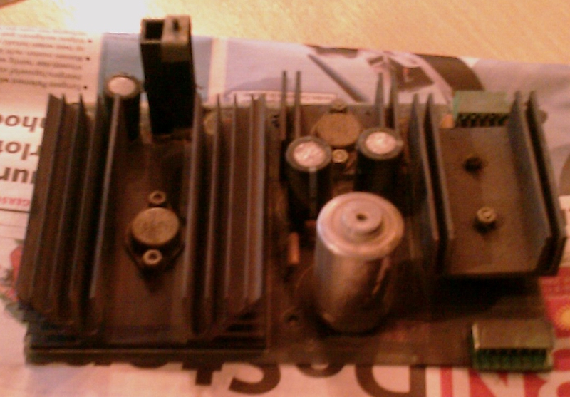
picked up the powerboard and as you can see it is a little dirty

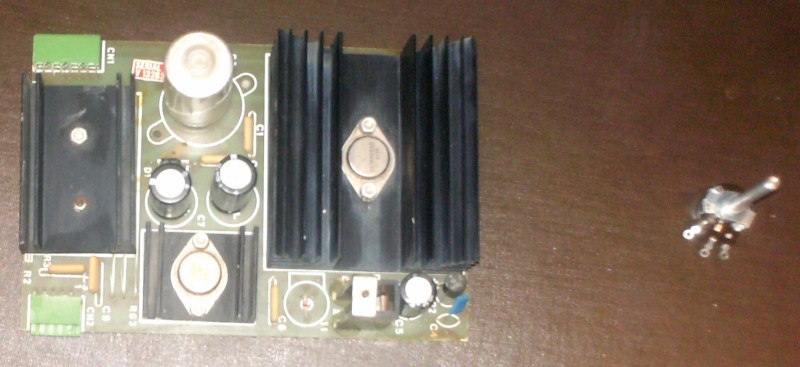
After some cleaning with a brush first, and later with some cloth it looks alot better.

My electronic supplier mentioned to me that the value of the pot (50 ohm) is "old" and that the only thing he has for me that comes close is 100 ohm.
Since the normal pot does the same job, i asked if he had that in 50 ohms, wich he did have.
I preffered a "onboard" variant, but because of the value issue, i went for the normal pot option, since i like to use the correct value
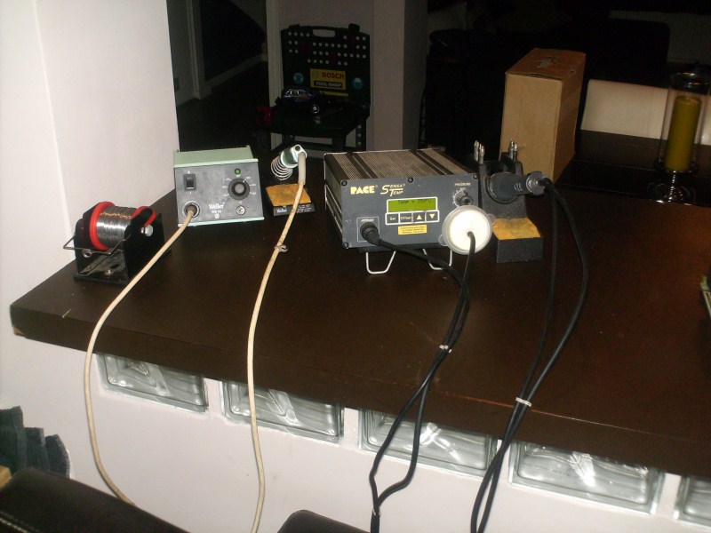
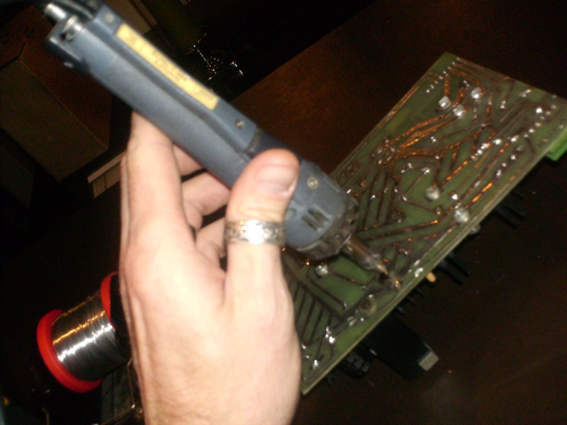
Solder tools in position, lets go !

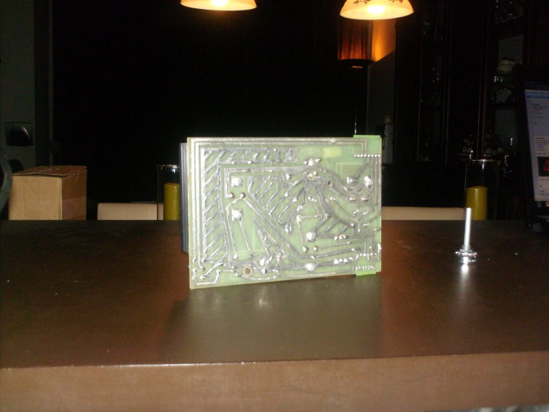
Look at that circuit!, totally tinned, i have not see that in a long time!
After adding a little fresh solder to flux it up a little, tin sucking in action! I love my desolder station

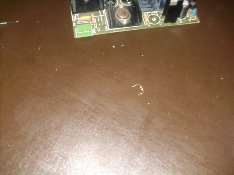
The reason why i love tin sucking is that after that the old part just falls out without hussle
The resistor i kept in a piece of paper wich i attached to the technical manual that i printed, if i want to reverse my modification, and then i have the original part

I am a little peter packrat when it comes to parts, so more than one year ago when i installed some servers on my job i had some spare cables that came with a kind of "net tule" wich i put in my laptopcase instead of trashing it.
I knew that there would be a day that it comes in handy.
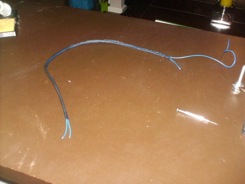
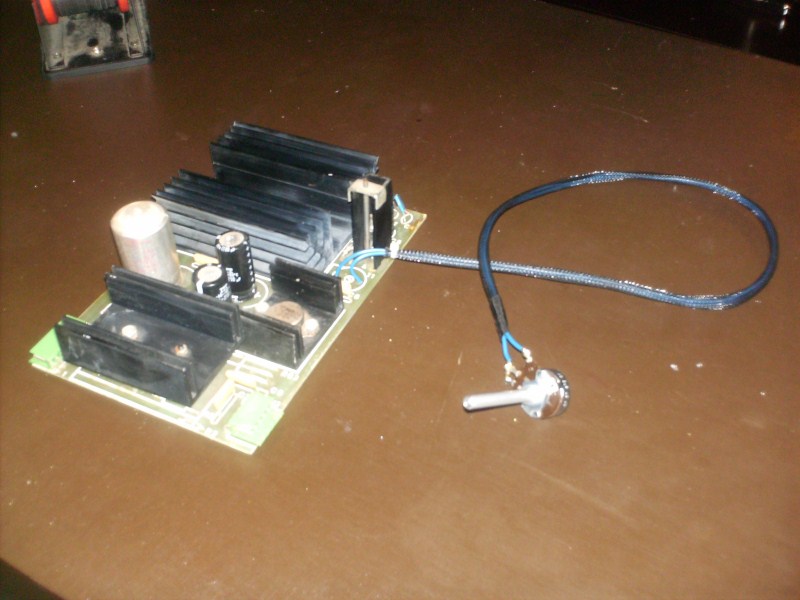
So because of the size of the pot i need to install some cable from the pot to the powerboard.

To create a very nice "extention" to the pot i used the tule for the cables.
Looks very professional IMHO

Thanx HP !
After soldering the wires to the pot, i adjusted the pot to the value of the resistor that was there.. 22 Ohms.
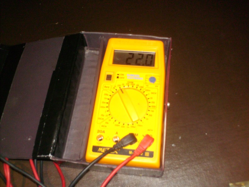
Modification complete !

Now i need to test it out, wich i did not do yet.
I have measured the values before the modification:
The "working board" FCK-01 (came with the machine)
11.95 volts measured on the board between pin 1 and 5
4.91 volts measured on the board between pin 1 and 9
The "other board" FCK-00 (from Level 42)
11.87 volts measured on the board between pin 1 and 5
4.66 volts measured on the board between pin 1 and 9
straight on the connector (without board connected)
12.05 volts measured on the connector between pin 1 and 5
5.3 volts measured on the connector between pin 1 and 9
The question now to you specialists:
Do i just connect the FCK-00 board, measure the 5 volt line and try to pump up the voltage to exactly 5V and reboot the machine then ?
Or what is the recomended way to go from here ?


