I got the +5V working today. There was no fault in the power board as I first thought, just a bad connection between the one of the fuses and the fuseholder. So I scratched the surface of the fuseholder a bit clean with a little screwdriver, and voila, the PCB connector spits out +5V. So there is a little progress again, +12V. +5V and +6.3V are working.
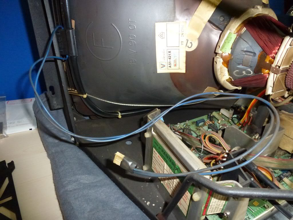
Now I'm trying to get a good working monitor/chassis combo. I took the A51-421X monitor which came out the electronolo (?) cab (
https://www.dragonslairfans.com/smfor/index.php?topic=3764.0) and I found a spare MTC-900 chassis which I had laying around for some years. Before I start fihring questions I should say that I don't even know if they are in working order. I guess we will see.
This is my first time to put a monitor and a chassis together, at least for a classic cab.
1. first question: It's a MTC-900 chassis. How can I tell if it is running on 220V or 128V?
2. if it is running on 220V, then I supposte that I only have to connect two wires from the 220V output of this trafo
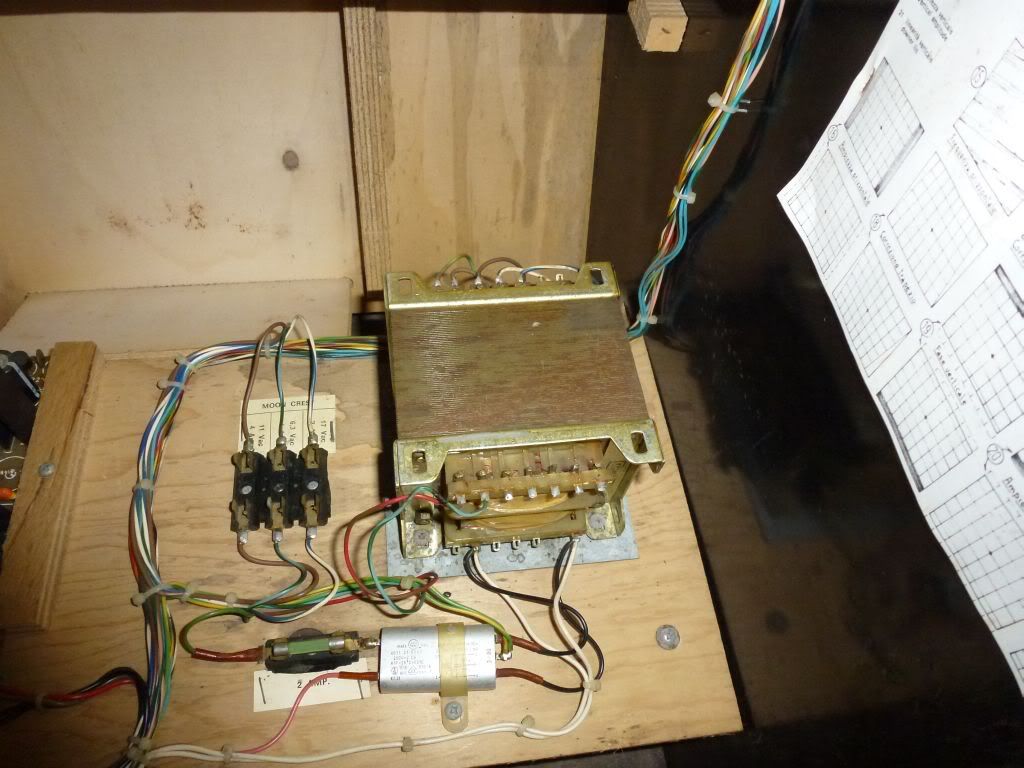
to the power input of the MTC-900? I should leave the 128V input for what it is (no connection needed or wanted)?
3. The neck of the monitor has 6 pins. Here the original wiring is still attached
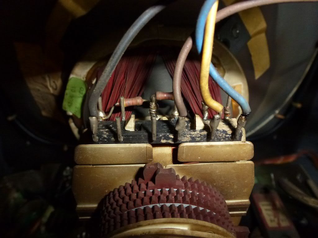
Now I connected the new cable loom at the MTC-900 chassis, but which wire (color) goes to which pin?
Am I correct if I say (judging the MTC 900 manual):
- Yellow (HY) goes to the 5th pin of the left
- Orange (HY) goes to the 4th pin of the left
- Red (VY) goes to the 3th pin of the left
- Brown (VY) goes to the 2nd pin of the left
subquestions:
- where stands HY and VY for?
- why are there six pins if you use only four?
- why has the connector on the MTC900 board 6 pins, but are the middle 2 connected by a wire loop?
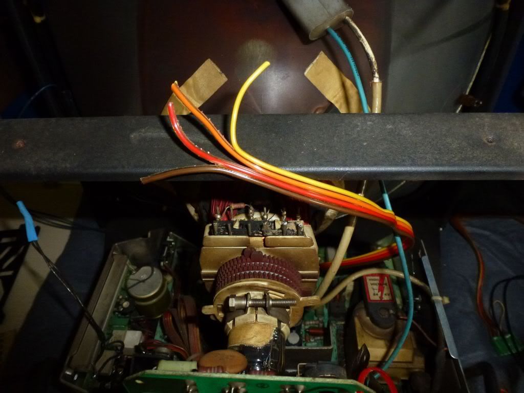
4. On the photo above you also see that the two wires coming from the degauss are taped together with light blue tape. Why did they do that and can I leave it like that?
5. what is the purpose of this cable
and do I connect it to this connector (next to the degauss)?
Edit: shoot, I just realized that it is the degauss wire running around the monitor.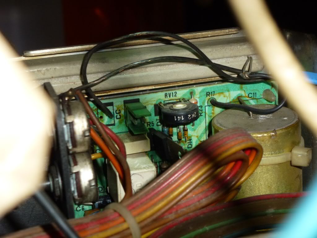
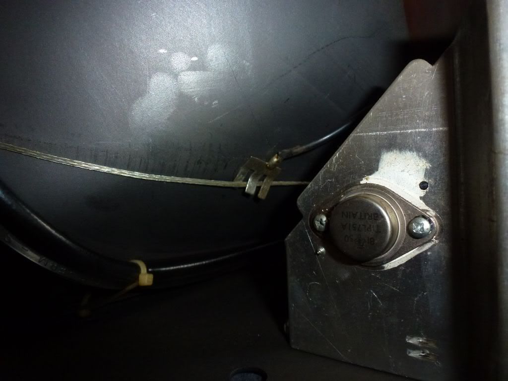
6. This black cable comes from the neck pcb. I suppose that it is ground and that I have to attach it to the bare wiring on the monitor back, like this:
7. What is the use of th little silver 'box' below the transformator? Is it some kind of filter? What for?
About the original MTC 90 which was in the Moon Crest. It was connected by the trago with 220V (2-pin connector on the MTC 90), but also with 15V and 143V (4-pin connector on the MTC 90). Why all the different voltages? I mean, the MTC-900 gets only 220V (or 128V) input.
One final question: everyring in the cab works on either +5V or +12V, but not the coindoor lights, they work on 6.3V. Why did they do that? Why not use also 5V or 12V for the light bulbs? Because 6.3V was common use?


