first you have to disconnect and reconnect the remote control board.
After you have to measure voltage +27V at the output of the power supply (on TP6).
If I remember correctly, the TDA1675 stop working below 24V
Otherwise, on theses boards, I've change sometime C139 (1000µF/35V), C137 (220µF/35V) or D127
measure on TP31.
Thanks Fred for these precise indications.

I'm gonna check that as soon as I can.
I'll open a dedicated topic for the monitor repair, and probably other ones for specific failures.
But for now, let's continue the first examination.
Oh yes, the documentation I got with the cabinet...
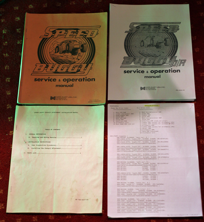
Well, it's not the one for this specific cabinet, but for the "Speed Buggy"Data East version. As far as I've seen, yeah, there are few similitudes, but most of the wiring in these manuals don't match the one on this TASTUMI version. In addition, none of these manuals includes boards schematics... it's better than nothing but I really have to find the manual/wiring/schematic for this specific cabinet model

So what is the 'engine' of that beast? :

The game board :

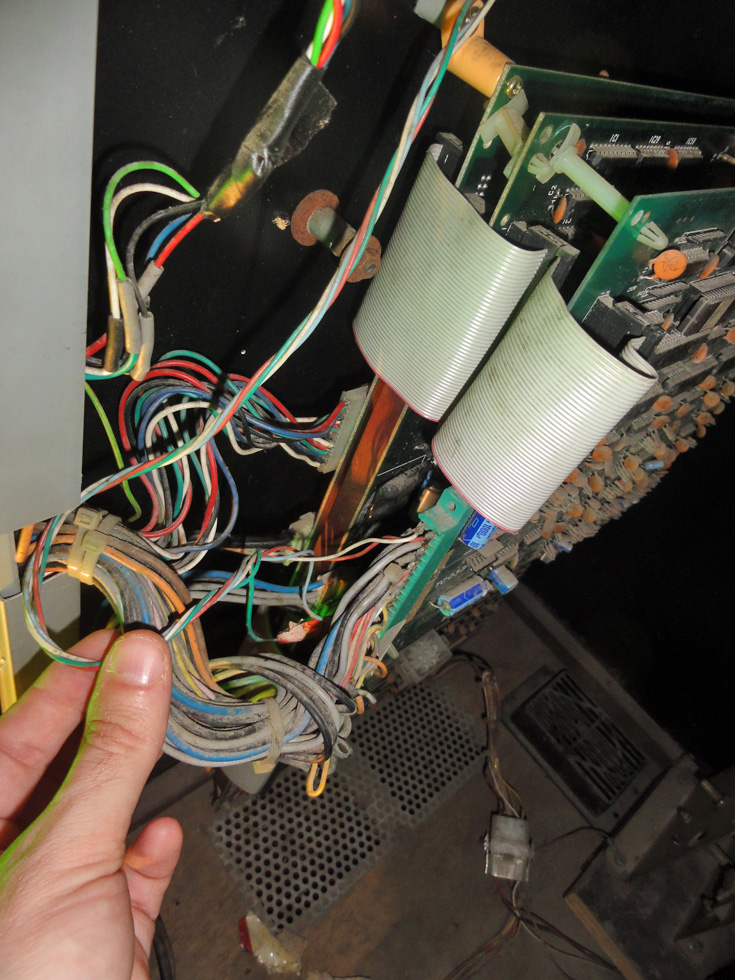
The 'lose' connector is -I would say- the one that goes to the rear/seat cabinet part I don't have, to be connect at the rear speakers?
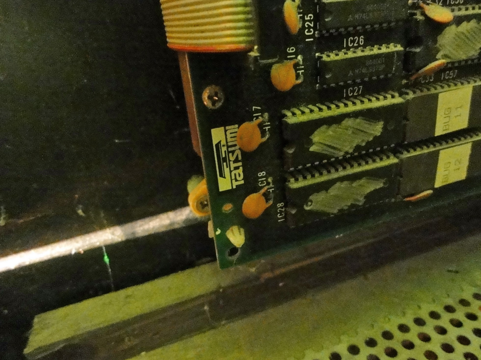
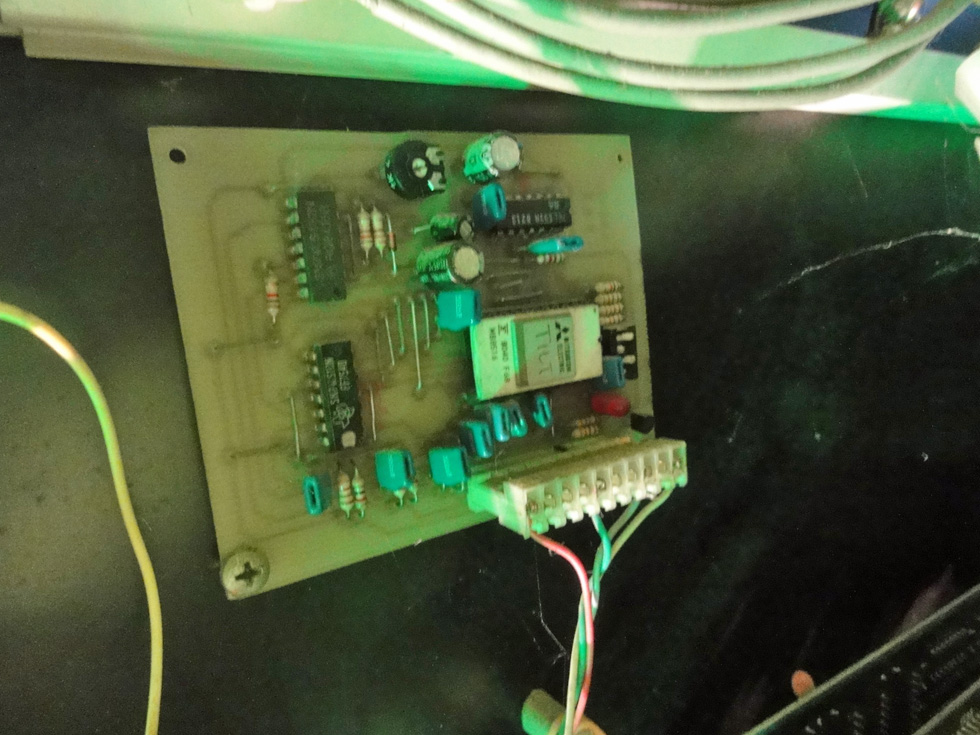
Original TATSUMI board (I'm wondering why scribbles on the ICs surface by the way)

It's a triple PCB (and there's even a fourth small mini-PCB behind the first/biggest one)
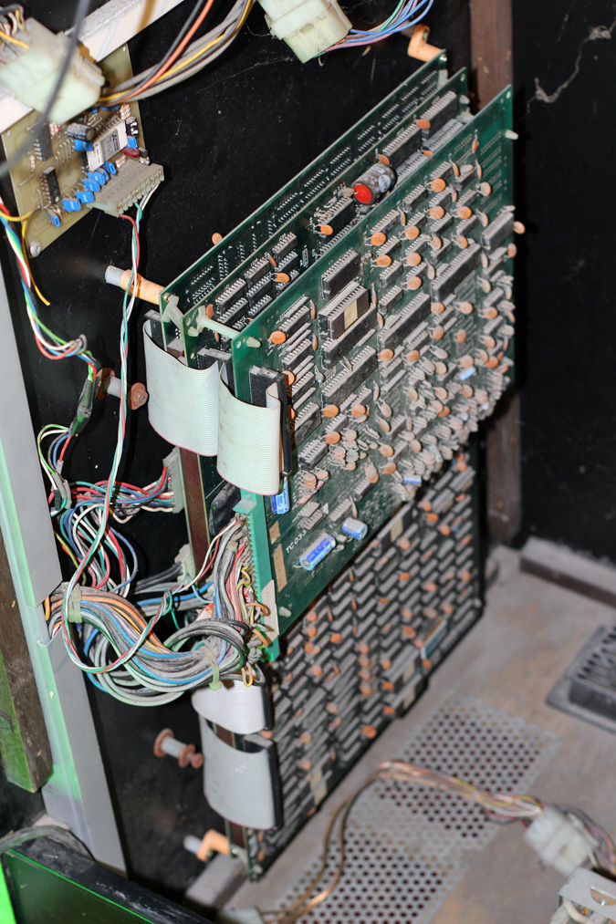
Few wires going to the main connector pcb have been cut/hacked/repaired?...dunno yet
Unknown board so far ...
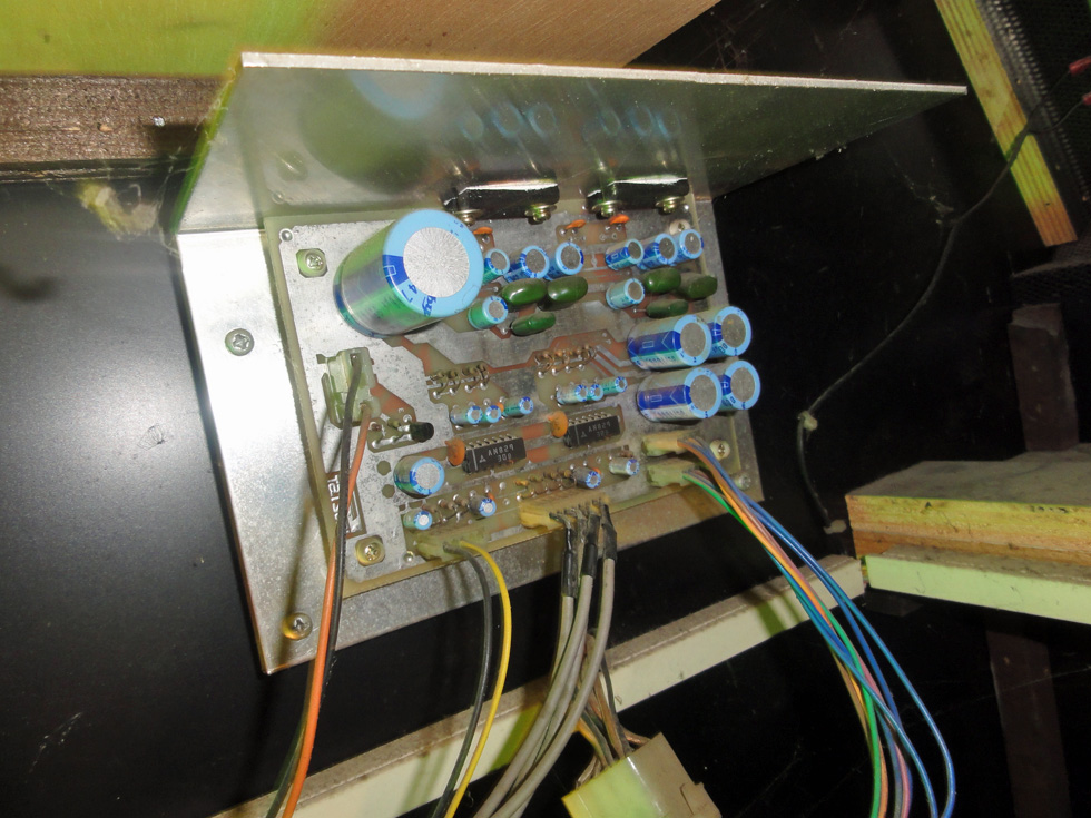
Sound amp board I would say :
Now I would be curious to know if the game board from the other version of the game (Buggy Boy Jr, Speed Buggy, single or triple screens) are similar to the one inside that Tatsumi version?


