As i am planning to build an arcade cab in the future, i was investigating the ways of connecting the controls.
As i like to spend as little as possible i focussed on hacking a keyboard.
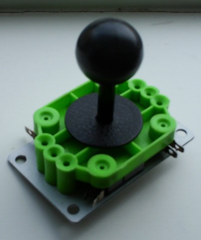
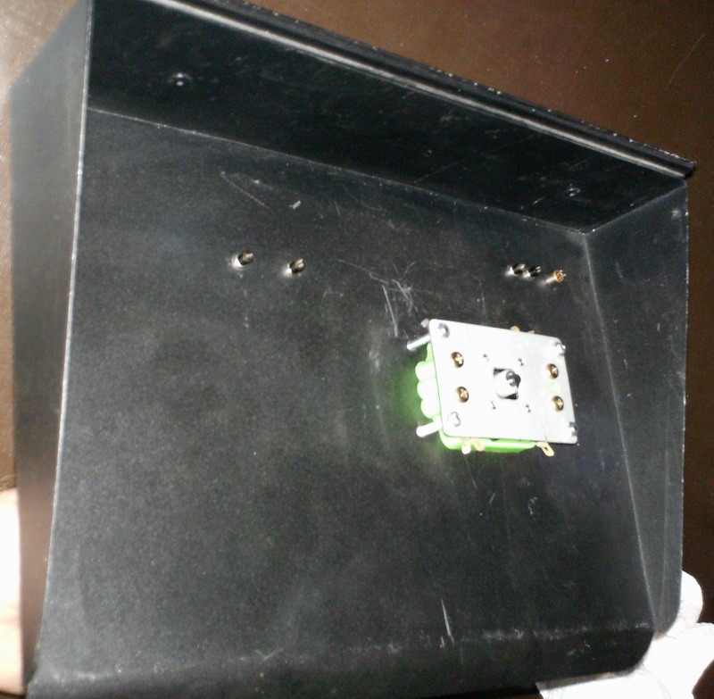
Somewhere i found this joystick that is good enough for testing purposes
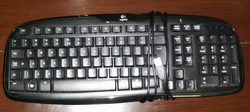
And ofcourse a "victim"

around 10 -15 € but i received it for free from a friend
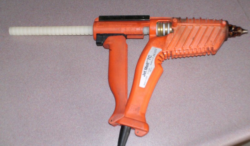
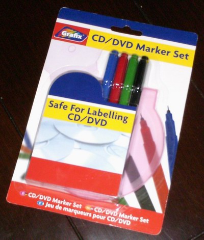
The tool of the day for this job

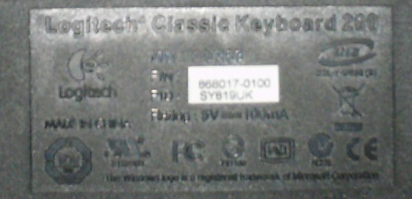
for the people that like to use this post as a tutorial, its a Logitech classic keyboard 200 USB
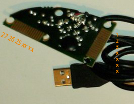
After taking out a bunch of screws, there is the treasure that we need

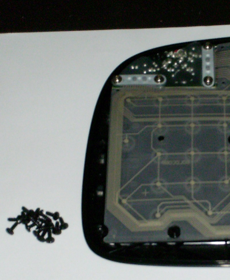
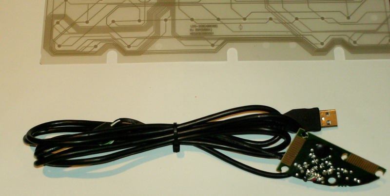
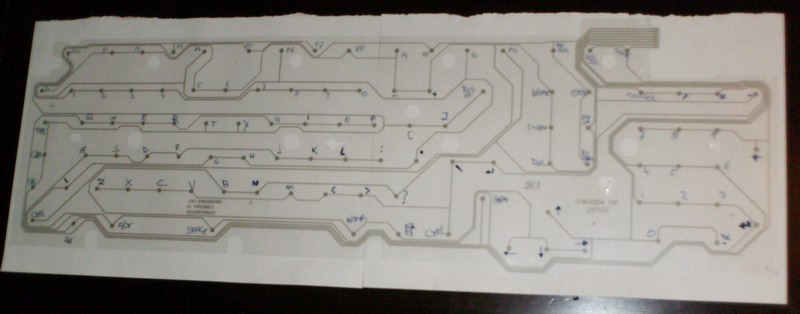
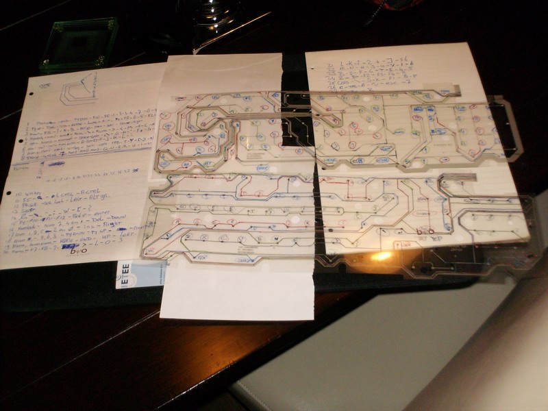
After carefully removing the controller its time for the "mapping of the matrix"
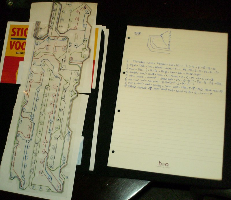
To follow all the lines on the circuit i used 4 different colors
First i write all the letters on the circuit after "splitting"the circuit
At the time i finished that i was not in the mood anymore to continue that day , so i put back together the remains
It makes a nice toy according to my son

Oke the tracing of the circuit can begin, i started to number the pins on the circuit , so that is why it starts on the controller with pin 27, and not with 1. the controller is mounted inside the keyboard in the opposite way than that i write

Can you folow me what i mean
Folowing lines....
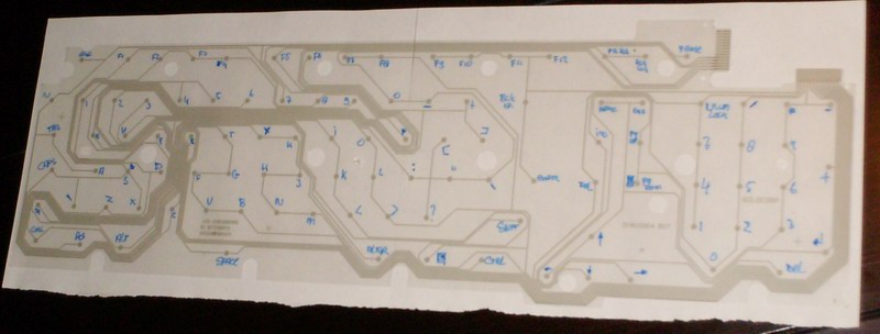
Following more lines.....
Im getting there !
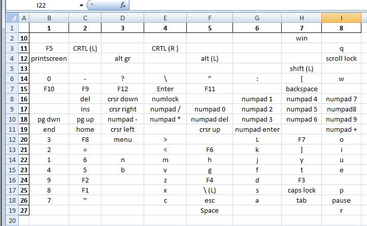
I made a excell sheet with the results (wich is handy for you if you like to use this KB for a hack)
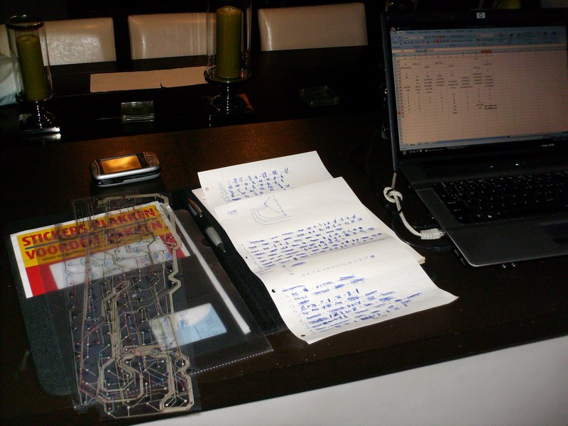
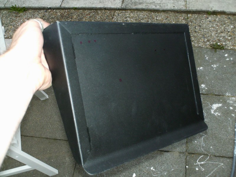
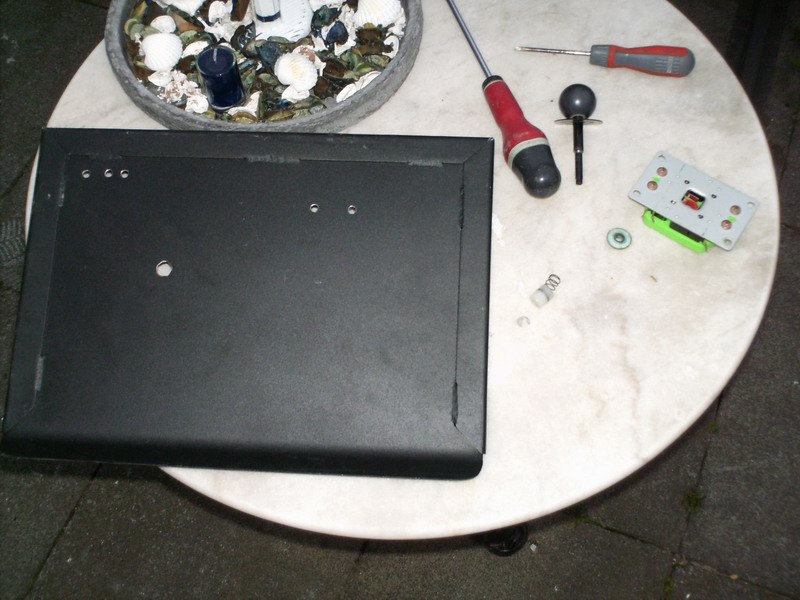
After this i decided to create a test panel from an old piece of metal
i already spend some time so why not continue...
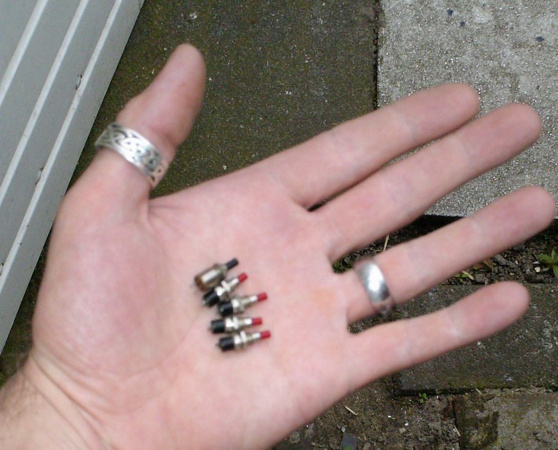
In some place i found some swiches wich could serve for the test panel
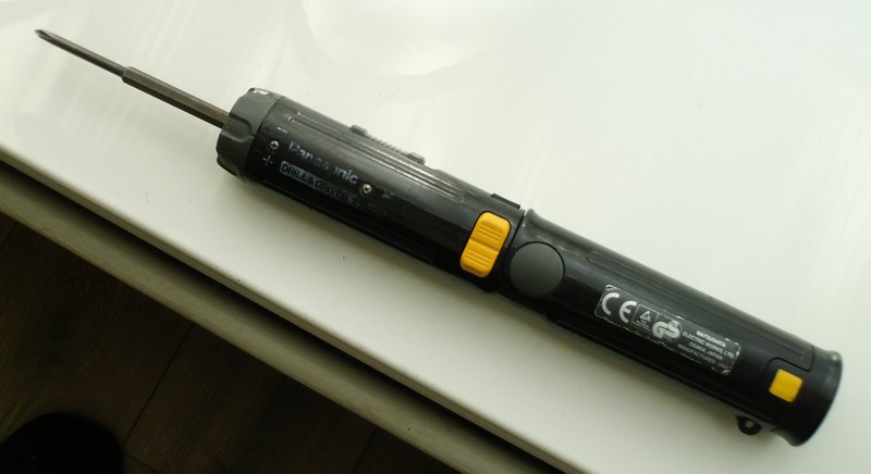
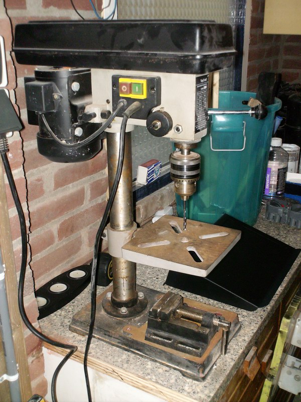
thanx god i have a nice tool for the drilling job

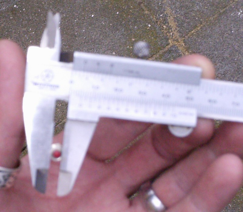
Measure the swiches (sorry for the blurry picture)
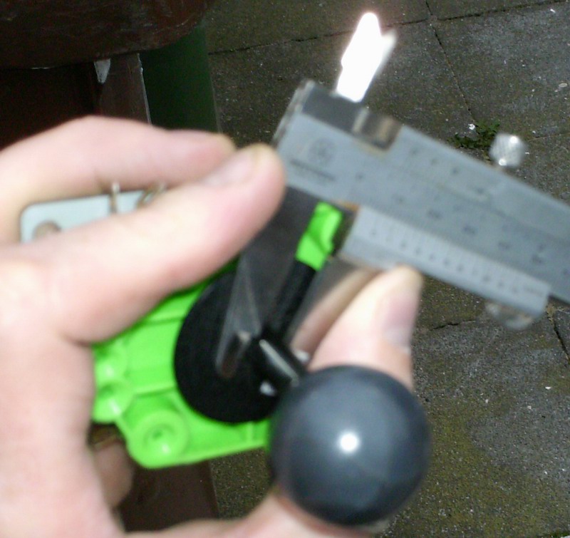
and measuring the joystick shaft
Holes drilled, ready to put everything together
These contacts need some sanding.....
after sanding
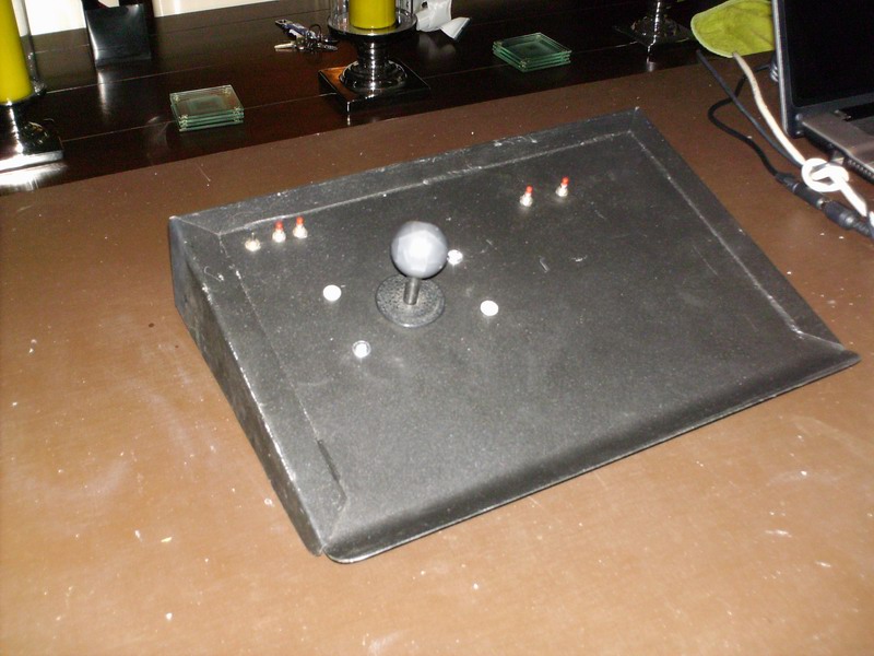
Everything in place
Bottom view
Solder time !
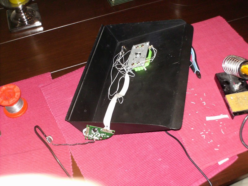
And finaly after soldering, and testing i used hot glue to mount the controller inside