Show Posts

This section allows you to view all posts made by this member. Note that you can only see posts made in areas you currently have access to.


Messages - c0dehunter

Pages: [1] 2
1
Glad to hear your observation. As I said, the PVM might look great for DVD/broadcast sources, but I am not that impressed with playing games on it (compared to my 1084S-D1 of course). Had I not seen it on my 1084, then I would have said that it was the best, but my 1084 is sharper, and the image stays centered and no need to adjustment.

2
To be honest, I am not 100% satisfied with the image quality of my SONY PVM-2030.

1) Compared to my 13" Commodore 1084S-D1, the scan-lines (which I love to have, don't get me wrong) are STRONGLY pronounced, and the actual R, G, B pixels standout prominently: Maybe this phenomenon is a feature of the Trinotron tube, but the image quality of my 1084S-D1 is much sharper/smoother. (Maybe it is the size of the 1084S-D1, but everything seems sharper.)

2) I managed to open my PVM-2030 and adjusted many settings, but I still could not get to produce the image that I came to love and adore with my 1084S-D1.

3) Using my SONY PVM-2030, when I launch different emulators, the image is completely off, so I have to spend time and manually adjust for each individual emulator. On my 1084S-D1, amazingly they stay pretty much centered and the way I like, (not to mention that 1084S-D1 features the adjusting knobs in the back for easy access, unlike the PVM-2030, which force me to leave it opened all the times for constant fine tuning.)

Obviously, this is a very subjective matter, but in my opinion, my 1084S-D1 is capable of producing a more sharper image. I will post some images to prove my observations.

After all the time and money spent, I guess I am back to my trusty Commodore 1084S-D1 for retro gaming emulation, but I think it was worth the try.

3
Here are the screenshots:


Geometry is OFF 01 by c0dehunter, on Flickr
As you can see, the red markers on top, right and bottom are missing, so the geometry needs to be adjusted.


Geometry is OFF 02 by c0dehunter, on Flickr
Again it needs adjustment.


Geometry is OFF 03 by c0dehunter, on Flickr

I would like to adjust the "bent" screen on the edges.

Are there images of a PVM opened? I can only see 4 screws connecting the back panel. Any help would be greatly appreciated!

4
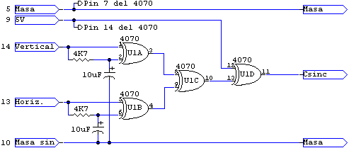
What circuit did you add ? I guess from reading your previous posts a bit better it is a sync combiner.

The picture must be very good this is a broadcast quality monitor :)

I ended up using this diagram:


At the following http://www.geocities.ws/podernixie/htpc/cables-en.html


It looks great and all but the screen is a bit off, and there is no knobs to adjust the position or the shape of the picture.

How do I open this monitor up for fine tuning?

Thanks.


Best,
c0dehunter

5
OK, I manage to have the person who originally made me the cable, also make the small circuit and implement it right in the 25pin housing, and guess what? It WORKS! It is a beauty to behold! (although compared to my 13" Commodore 1084S-D1, it would take time to adjust to its nice 20" size!)

Thank you all for your kind comments which made this project a success! I will post images shortly!

Thanks again.

6
Is the picture stable like that or does it also move ?

It definitly is a sync issue. Did you try adjusting the horizontal sync of the monitor ?

Thanks for your message. The picture moves a bit and as you see is distorted.

when it is OFF, I get NO picture at all. When I turn it to ON, I get the image, but as you can see, it is distorted.

7
OK, I found a local solder-guy who make me this cable, but when I connected it, this is what I got:

http://www.flickr.com/photos/48901682@N02/7688576136/in/photostream/lightbox/
http://www.flickr.com/photos/48901682@N02/7688574312/in/photostream/lightbox/

In reality, the above image should look like this:

http://www.flickr.com/photos/48901682@N02/7688572754/in/photostream/lightbox/

But looks like this:

http://www.flickr.com/photos/48901682@N02/7688574312/in/photostream/lightbox/

These are the images of the 15pin (VGA) solder work:
http://www.flickr.com/photos/48901682@N02/7688571564/in/photostream/lightbox/
http://www.flickr.com/photos/48901682@N02/7688570620/in/photostream/lightbox/
http://www.flickr.com/photos/48901682@N02/7688570024/in/photostream/lightbox/
http://www.flickr.com/photos/48901682@N02/7688569412/in/photostream/lightbox/


These are the images of the 25pin (Sony PVM-2030) solder work:
http://www.flickr.com/photos/48901682@N02/7688568768/in/photostream/lightbox/
http://www.flickr.com/photos/48901682@N02/7688568128/in/photostream/lightbox/
http://www.flickr.com/photos/48901682@N02/7688566900/in/photostream/lightbox/
http://www.flickr.com/photos/48901682@N02/7688566216/in/photostream/lightbox/

Both connectors together:
http://www.flickr.com/photos/48901682@N02/7688565432/in/photostream/lightbox/
http://www.flickr.com/photos/48901682@N02/7688577078/in/photostream/lightbox/

Diagram
http://www.flickr.com/photos/48901682@N02/7588180386/in/photostream/lightbox/


Everything seems to be in order, but I am not sure why I get a distorted image. I even tried it with another computer (which has a compatible Soft 15Khz video card) and had the exact result, so it must be the wiring.

Any suggestions are greatly appreciated.

Thanks.
 

8
I`ve lost a good link ;)

But for first just solder them together. Should work. On the UMSA I use 4060 IC plus some elkos. But this is a overkill for your needs.

Hello bencao74,
Thanks for your message, I really appreciate it! Yes, I am going to just solder them and see what happens. Another option is that I have a good, unused 25pin (one end male, other is female) so I can cut it and connect (and match!) its wires to a cut ready made VGA cable.


9
Thank you kindly for your posts. How do I make a "composite" H and V signal then? Apparently, I can simply connect them, somehow they need to be made into a "composite" form:

http://www.assemblergames.com/forums/showthread.php?4774-25-pin-D-sub/page2&s=400b38312173d2901c016044cede0409&highlight=Sony

"I thought you needed some sort of magical logic chip to combine H and V sync?"

ou'd need to divide the H sync and combine them to get composite sync, I think you can divide Hsync with a D-type flipflop.

As you know, my video card is already compatible with Soft 15KHz (connected to my 1084S-D1 monitor)

Any help on H and V signals is greatly appreciate!

10
Thank you so much, one quick questions: what does the user in other forum means when he says that I have to combine V and H signals to make a composite one? (my video card can already send a 15Khz signal via Soft 15Khz to my Commodore 1084S-D1 CRT monitor)

"you need to convert horizontal sync and vertical sync into composite sync, as a PVM-2030 won't accept separate syncs when feeding analog RGB."

I really appreciate your comments, you are the best!

p.s. hey bencao74, I love your blog and website, very interesting stuff! keep it up!

11
You don't have SCART, but I just checked the Sony PVM-2030 manual and it has both analogue and digital RGB inputs.

The analogue one's are the same function as SCART RGB would provide....

Thank you so much for your response. Do you know how can I make a custom cable 15pin VGA to 25pin Sony?

This is a diagram that I made based on table provided by the user named RGB32E
http://www.flickr.com/photos/48901682@N02/7588180386/in/photostream/#/photos/48901682@N02/7588180386/in/photostream/lightbox/

I am not sure when I tell the person who is about to make this cable for me how to make it, If I have him solder R, G, B, H-Sync, V-Sync, Ground, will that be suffice?

Thanks so much for your time!


12
Well, thanks for the reply but my Sony PVM-2030 is a NTSC model and does not feature SCART (I live in North America). As for the forums, it seems informative, but unfortunately it is in German and I don't speak the language! :-[

13
Etienne, thanks for responding to my question!
OK, the thing I am not sure is this: I thought it is easy to connect this Sony PVM-2030 to a VGA, by connecting RGB, V and H sync and GROUND. In these forums, they talk about Composite sync and an ADDITIONAL device which combines the H and V signals:

http://nfggames.com/forum2/index.php?topic=4028.msg32178#msg32178

User RGB32E states that:

"The PVM-2030 doesn't accept separate sync when analog RGB signals are used.  A sync combiner is required to convert RGBHV to RGBS.
The PVM-2030/2530 don't actually accept separate sync signals when analog signals are used. You'll need a device (extron RGB interface) or circuit (ask google) to convert the separate sync signals into composite sync (RGBHV to RGBS)?"


I think he is talking about connecting various real gaming consoles (SNES, SEGA GENESIS, etc) to this monitor. But all I am trying to do is EMULATION: using a modern PC and playing games using MAME and other emulators. For this purpose, I need to make a DB25 (Sony) to DV15 (VGA) custom cable and connect Sony PVM-2030 to my modern PC. My video card can send a 15KHz video signal using Soft 15KHz software (I am playing emulator games right now, connecting my PC to my Commodore 1084S-D1 and it looks great!)

Additionally I know this guy also was able to connect his Sony PVM-2030 to his PC without any sync composite device:

http://nfggames.com/forum2/index.php?topic=4656.0

The more I think about it, the more convinced I am, that the reason RGB32E was talking about composite sync on Sony PVM-2030s is because he thought I was going to connect real game console this monitor.

14
Hello All!
OK, I am about to make a custom cable in order to connect a Sony PVM-2030 (with 25pin connector) to a modern PC's VGA (15pin), and use MAME and other emulators (currently I am connecting my Commodore 1084S-D1 and it looks great!)

The VGA to 25pin schematic table is as follows:

http://www.flickr.com/photos/48901682@N02/7588179296/in/photostream/lightbox/

The table comes from this forum post, however the actual diagram is INCORRECT:
http://nfggames.com/forum2/index.php?topic=4028.0

I was determined to make a CORRECTED diagram, so I made this diagram instead:
http://www.flickr.com/photos/48901682@N02/7588180386/in/photostream/lightbox/

The question that I have is this:
In the original table, it states that pins 15 to 24 are GROUND (corresponding to pins 6,7,8,10 on Sony's 25pin connector in the back). Do I need 10 (ten!) cables to ground these pins?

I can solder pins 6, 5, 4, 3, and 11 (R, G, B, H-Sync, V-Sync) but I am not sure about Ground pins.

Would you kindly let me know what pins (how many cables!) I need to ground?

also why the person who posted this table (RGB32E), states that: "The only pin you could optionally ground is pin 2 - audio select."

Any help regarding grounding those pins are much appreciated!


15
Thanks! I will. I really appreciate your help and great notes!
 :wink:

Pages: [1] 2