Show Posts

This section allows you to view all posts made by this member. Note that you can only see posts made in areas you currently have access to.


Topics - smarty

Pages: [1]
1
Here's another fix I hope you enjoy reading... I've posted this elsewhere on the web I'm sure some of you will have seen it already, but for everyone else  :ghost: :ghost: :ghost:

So part of my Cocktail restoration was to fix the Super Breakout game board that came with it. I knew it was faulty after my initial taesting of the cab a few months back.

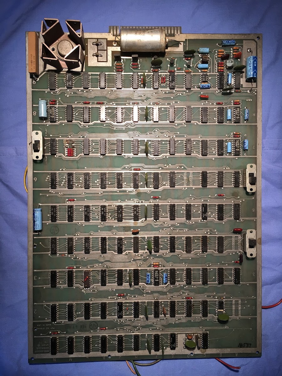
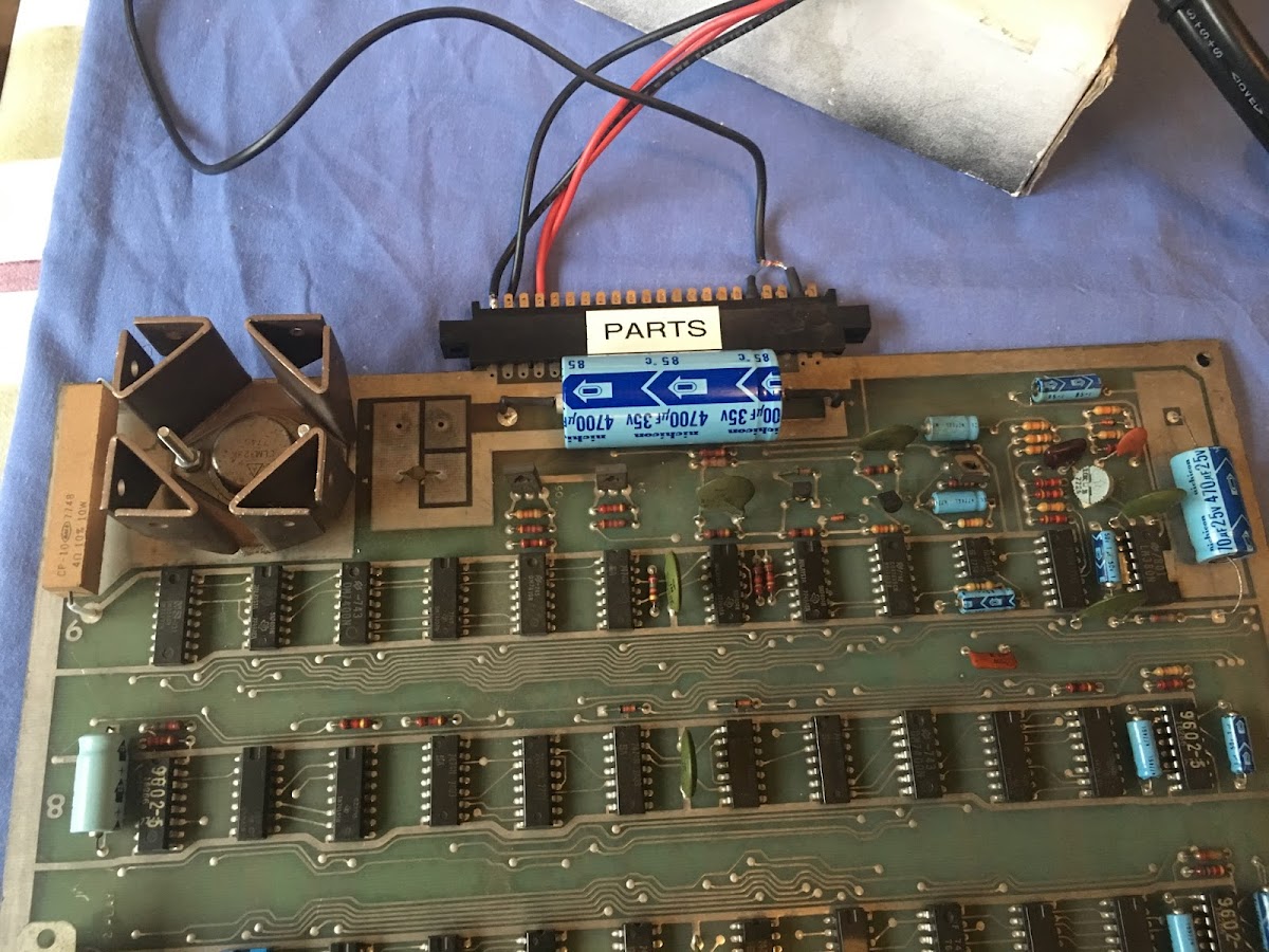
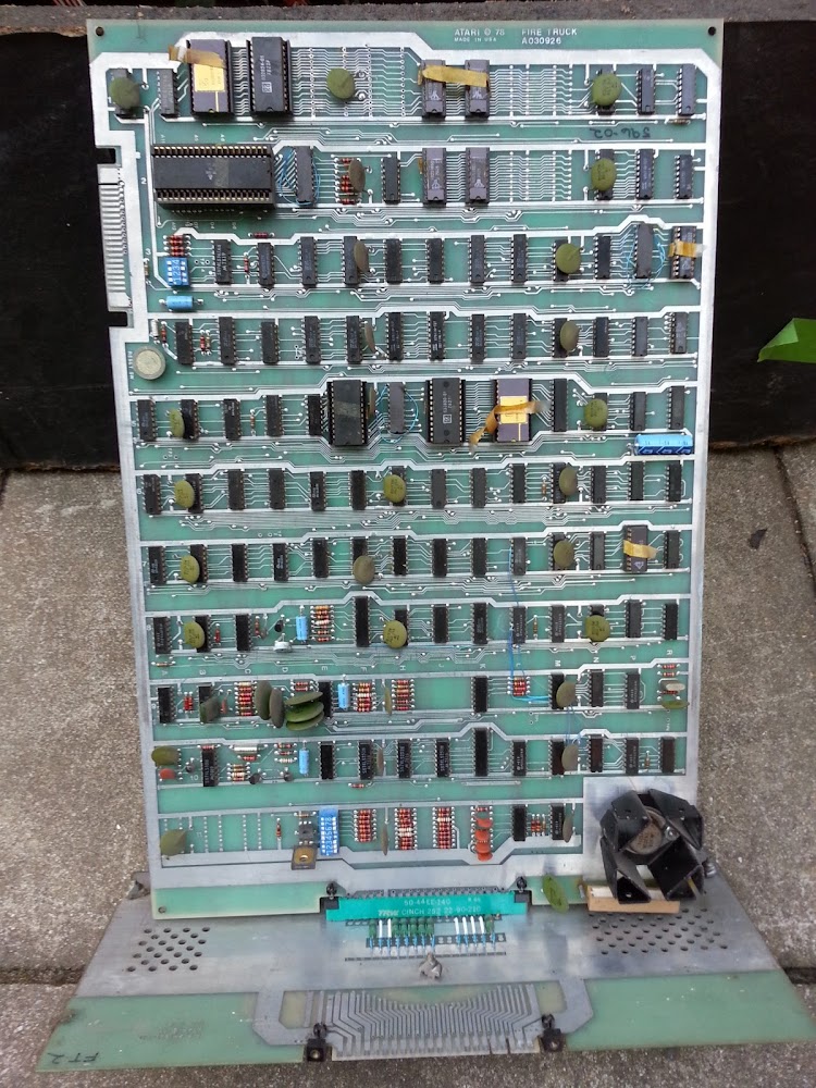
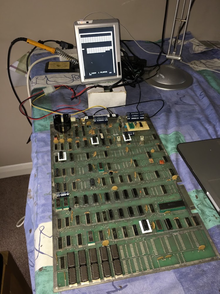
The board itself has now manufacturing marking or anything to say who made it. From studying photos of Atari boards this appears to be a direct 1:1 copy of a Rev-03 board. The only difference I noted was changing of the audio amplifier which would be a TD1004, this PCB has an LM380 on a small daughter board that plugs into the TDA1004 socket location. Image below showing the PCB in its original faulty state. 


When plugged in with a basic adaptor providing 5V DC for the game logic and video output to my monitor. The game was displaying garbage on the screen that was almost static but some characters did move and change here and there. The game looked the same in test mode as well.


So checking the reset line on the CPU (pin 40) it was constantly changing state when it should have been held high after the initial board power up, this means the game code is not running correctly for some reason and the CPU is being restarted to try and get the game code from the ROM's running and initialised correctly.

After a few more quick checks of the clock signals and confirming the address & data bus were active, I took a look at the signals on the main ROMs the run the game program and found 3/4 of the ROM select lines we not active. From memory one had no signal and the other two were stuck high. THE IC location was F2 and is a 3901 chip which is obsolete and unobtainable, With the help of someone on the DLF forums and PhilMurry I had some converter PCB's made up which worked with a 7442 IC.

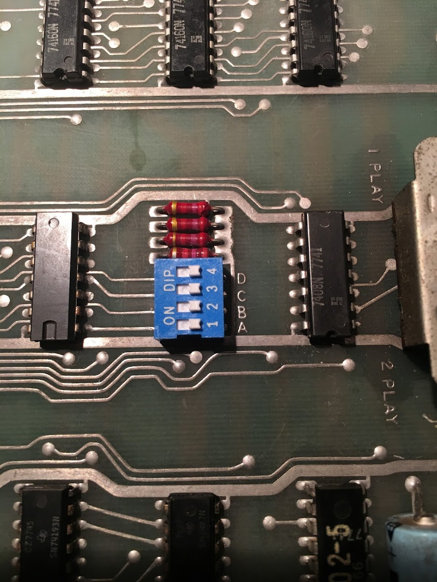
I had previously made a very rough adaptor show below,


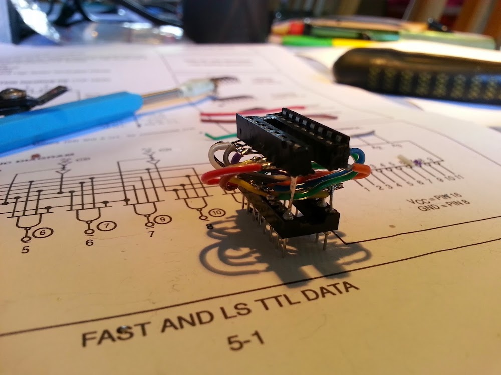
These new adaptor boards are a vast improvement!


Changing this IC got the ROM select lines active but the game was still resetting and the screen was full of garbage still.  Checking around the reset circuit I found another 3901 IC that I suspected was faulty. This one at location E8 should have been triggering a Timer Reset signal which if working correctly would clear a timing circuit that stops the CPU from being reset assuming everything else was working OK.

Next up I decided to check the RAM with my logic probe, visibly using the probe all the signals were active, but I had little other way to confirm if they were working as the game was not running. I decided to remove all eight RAM's and socket them. I then fitted some new 2102 ram, using this method once the game was running I could put back the original RAM and confirm which one did or didn't work.


So with all eight RAM's changed we had what look like part of the Playfield being drawn but not a lot else. The CPU was still resetting so the code still wasn't running correctly.


Flicking the game into test mode the display was now stable and showing a ROM error, a good sign. This ROM was at PCB location L1. I removed it and cleaned the chip legs and fitted it back in the socket.


Boom! the game was running, but the balls we just faint 'dots' on the screen and not moving correctly. More diagnosing found another two 3901 IC's that were faulty, each of these IC's should have been sending ROM and position data to the Motion generator circuit where the balls and their movement is calculated. These two IC's were at locations K8 and P7, the upside of fixing this fault was that it also fixed an audio fault i hadn't yet discovered! The IC at P7 and output signal (*TONES) on pin 11 was stuck high. This is an enable line for the audio latch that combines data signals and turns them into the game sound. I check with an audio probe and found I had a constant garbage sound playing when in game and test mode.

So with those two IC's replaced the game looked to be playing, test mode showed no problems, but the balls were being doubled up, each of the three balls was being generated twice, they were tracking each other and moving in an identical pattern, they just shouldn't have been there. I thought this would be an easy fix...


Fast forward Seven or so hours of faultfinding I found the problem. Now this was something a Logic probe and an Oscilloscope couldn't help find.

Eventually the only IC's I was left with that could have something to do with the problem were a pair of 7483's they are used as comparators to compare a RAM value with the vertical line that is being displayed, if they match three load pulses are triggered which are used by the video shift registers.

I didn't have replacements for these but decided to remove them and fit sockets. I intentionally put them back in different positions, and the fault appeared to be gone. Fitting them back into their original positions the fault came back. Looking at the schematics we can conclude that the IC at M4 had a faulty input on pin 13. I will temporarily use them but have ordered some new replacements.


A final look at the board wired to my test rig. The total IC's replaced is as follows:

F2 - 3901 - ROM Selects
F,H,J,K4  - Ram 2102
F,H,J,5     - Ram 2102
E8 - 3901 - Reset circuit
K8 - 3901 - Ball motion circuit
P7  - 3901 - Ball motion circuit & Sound
M4 - 7483 - Ball motion circuit


The game has been play tested in the cabinet and all controls, sound, Input and Output all work correctly.

If you made it this far well done!

Thanks for reading, Mart. :)


2
Technical Area / Atari Breakout PCB repair. Work In Progress
« on: November 29, 2016, 09:48:30 PM »
Part 1

So I was given this Breakout PCB earlier in the year and thought I'd fire it up and see if it worked.


First up the PCB was covered in lots of wires that were soldered onto the board but with nothing connected to them, some sort of previous mod that had been removed.


I de-soldered these wires and re-made a trace that had been cut on the PCB.

Visually there were a few IC's missing and one that was broken almost in half and partially de-soldered. After looking up the IC locations in the Ops manual, all three were 74LS08's, clearly someone needed them for something else! The solder pads were cleaned, new sockets fitted and IC's fitted.


Next up was the big filter Capacitor near the edge connector. This was clearly past its best so I replace it with another I had in my stash.


There were four wire links on the board which denote the game bonus given depending on score. These were a right mess where I guess they had previously been moved around. I removed the links and fitted a nice new 4-way dip switch block similar to what all the later Atari games have.


Next up it was time to make a basic loom to apply power and get some composite video out of the game.

Looking at the high level wiring diagram for the game, the power input comes from a 16.5Vac centre tapped transformer, which via a couple of diodes feeds the audio amplifier and then into an LM323 regulator which provides the regulated 5Vdc for the game logic.

From previous experience with these old Atari Black & White games I know you can happily run these games from a 12Vdc power supply as long as it supplies 3 Amps of current if the have an LM323 regulator.. Most JAMMA switcher supplies wont work as they don't provide enough current on the 12V rail. With power connections made to an edge connector I looked up the pins for the Video output and it's ground connection and wired these to a phono (RCA) connector which would plug into my video monitor.

With only these connections made I should be able to see if the board is dead or alive, or somewhere in between.

One final check I decided to make was to confirm that the 5V rail and the Ground rail on the PCB were not shorted to each other, this was confirmed as being OK with my Multi-meter set on continuity test.

Time to fire it up!

So with monitor connected to the video cable and the edge connector plugged into the PCB I powered it up...


Not bad... The board has a video output, which is stable apart from some image tearing on the right hand side, I'll need to confirm if this is a fault with the PCB or if my monitor is struggling to sync to the signal.

You can see the score numbering along with the numbers indicating which player is 'up' and which ball is is in play. There are clearly not correct, but the fact they're being show is a good sign.

There's no playfield of bricks, a players paddle or any balls flying around the screen so the board at this point so I need to investigate further to see whats going on.


So next up I need to make connections for controls, and coins switches etc, then I'll print the schematics and get out my trusty Logic probe.

To be continued...  :)

3
'Business' Area : Buy/Sell/Trade / WTB: G05-805 HV Board
« on: November 14, 2015, 03:48:03 PM »
Hi guys,

I'm fixing an Asteroids cocktail for a friend and I'm 99% sure I have a shorted LOTP on a G05 HV board. I have spent a fair bit of time working on the monitor and have proven all the discrete logic & transistors are OK, I had a few faulty components on the way that have been replaced, but from my testing is can now only suspect the LOPT.

If anyone can help with a spare board that would be great, I don't mind if it is faulty, I would really like to get the game working again soon.

Thanks, Mart.  :)


4
So, my Pole Position board had been working perfectly for a year since its last repair, it's had regular play every week and in my eyes it wasn't a scary event turning the cab on, expecting the a bad outcome.

A few weeks ago I play a game on the cab entered my initials at the high score page and moved onto another game, 10 minutes later I took a peek at the screen and something had gone wrong... The attract mode scoreboard and the title screen all worked fine, but during the screen showing the cars, the track was missing and the background and clouds we gone :(


Grass tracking instead of GP racing.


All the scores, timings, signs and other cars were present, the track had gone walkabout... After a couple of re-powers and checking of test mode for RAM & ROM failures, I knew the board had thrown its dummy out of the pram and would need some attention.


Test setup for testing.Power and video only at this point.

Well after being on the test rig for a very short time, the image deteriorated even more than when it failed in the cab.


Things getting worse...

To me it looked like the 'Green' video signal in the track elements were now missing, the signs and the cars had notably changed colour.

After some extensive google searching for possible faults I came across one post on KLOV arcade forum saying that if the custom IC's 5L or 6L from the Video PCB are removed, you will get the the exact fault that my board originally had.

I did have a spare Video board that had never been powered on, my first test was to swap the two custom IC's around, luckily they are socketed so that didn't take more than five minutes to find I still had the same problem with them swapped out, it would have been unlikely all four were bad so I moved on to some 'real' fault finding.


Video circuit showing the two Custom IC's mentioned above

With a logic probe, all the input and output signals looked busy pulsing away, signals 'PIC1-4' feed into an 74LS157 Multiplexer at location 8C.


74L157 at location 8C on the Video PCB
With a logic probe I moved through the input signal and everything looked well, moving to the four output signals pin four was stuck low while the other three outputs were pulsing away. I fired up my scope to look that what was coming out of the output pins, and even on the three outputs that were pulsing away, there wasn't much data on the signal and the output on pin four was definitely dead.

I did a quick piggyback test and when fires up the green grass seemed to be back and I could see an outline of the track but it still looked pretty messed up. Anyway, I removed the IC, put a socket in and pressed in a new 74157. With finger crossed I powered the game up and was gladly met with the game fully working again. :)


Pole Position lives again

With the game fully working I did confirm that removing either custom at 5L or 6L will exhibit the same fault my boar had when it failed.

Boom! Thanks for reading, more PP repairs to come in the future. I've got a CPU board to look at, it doesn't boot, and I also have a video board that has a graphic fault in the mountains and clouds.

5
Technical Area / Atari Super Breakout PCB. Back from the dead...
« on: March 14, 2015, 09:59:38 PM »
Well a few weeks back I picked up a new cab, a 1978 European (French Built) Atari Super Breakout. Bought in an unknown condition, it turned out the only faults were with the game board (No surprise there !) and the LED on the Serve button being blown. The photo below shows the cab with my test generator plugged in in need of a good clean.


After confirming all the cab voltages were correct & present, I plugged the game board in to be greeted with a black screen and some very faint horizontal lines running across the screen. To get this running in a test rig I re-used my FireTruck/SuperBug adapter as the pin outs for these games are similar, well the Power and Ground signals to make the logic work are on the same pins. I added a few new links on the adaptor to supply my monitor with Composite along with a few switches for Coin-up, Serve and Test.

Now on my work bench, (AKA the Dining room table) the board gave the same symptoms as in my cab.

First I checked using my logic probe to see what the CPU (6502) was up to. Pin 40 of the CPU is the reset pin, this was constantly pulsing high and low when it should be constantly high after an initial low at power on, from this we know that the CPU is not running the game code from the ROMS.

Next to check was the clock circuit, Pin 37 of the CPU is the clock input, this pin should have a nice clock signal on it but there was only a low signal and no pulse. I then went right back to the start of clock circuit and checked the 12Mhz clock and the circuit where the frequency of this is divided down to the Horizontal & Vertical timings that keep the board running in time.

All the H&V clock signal checked out OK which the took me back to looking closer to the CPU clock input. There are three IC's directly involved in making the clock input for the CPU run. As it turned out all three were faulty. A74LS20 @ A8 had a dead output, this fed into a 74LS174 which had a bad output on pin 12, this connected to a 74LS32 which should provide the CPU clock signal, this output was stuck high with no data pulsing. Once all three were replaced and confirmed as faulty, the clock input was looking good, clock outputs 1&2 also came to life now, address bus and data bus lines were active but something was telling me the pulsing I was seeing was not right compared to what I have been getting used to recently while working on board repairs. The game was still resetting.

Following the path of the Address bus lines there was an IC @ F2 labelled as a 3901 on the Atari schematics, the outputs of this device are the PROM select lines. All 6 used and the for unused output were dead, Not high, not low  but completely dead. Researching what this IC was and where I could source a spare I found very little info other that a post in a pinball newsgroup from 2007. the 3901 was a '1 of 10' decoder and seemed to now be unavailable anywhere, to me this looked like a similar decoder, the 74LS42 which is used in other Atari games I've worked on, the only difference seemed to be the pin out, so I had to make an adapter to convert the 74LS42 pin out to fit how the 3901 was wired on the Super Breakout PCB. I decided to know up a IC socket to socket adapter with wiring to convert the pin out. The finished item is below, it's not pretty and at the time I wasn't quite sure if it would work, but it had to be better than an IC with no working outputs.


Pin converter for 3901 -> 74LS42 one-to-ten decoder

Upon power up we now had some garbage on screen, the CPU was still resetting but I was making progress :) All the other important signals which should make the game run were present but again the way the pulsing looked on my probe made sure something else was still pretty sick on the board.


Messed up screen, system still resetting and not running properly

I next decided to socket and replace the eight 2102 RAMs. I have no way to test these so for now putting new replacements in would hopefully help me get the board working, I'd then be able to test them once the board was working. After swapping these there was no difference to the above screen. I decided to try swapping the CPU with a known worker, my Missile Command PCB now comes to the rescue... After swapping the 6502 over the game comes to life! Watching Attract mode shows the blocks disappearing with no sign the balls.


Game now running with invisible balls!

The game wouldn't start or go into test mode and as mentioned there were no balls in attract mode. The Coin, Start and Test inputs are pass through a 74LS153  @ M8, the output pins from this IC were both stuck high, removing and testing it confirmed it was faulty. After swapping the 153 the game would start and would enter test mode. Test mode gave no errors so things were looking good other than the missing balls.

The three 'balls' video signals are derived from a bank of six 74LS163's, piggy backing two of the six with a known good device made two balls return. These two were removed and replaced, the third ball couldn't be found by piggy backing on another '163 but I used some guesswork and removed the IC I thought was the problem, It did turn out to be faulty and once replaced the game looked like it was fully working. The three '163's (Locations R6, P6 & N6) were tested and confirmed as faulty as shown below.


Tester showing faults on 74LS163


Great balls of Breakout! They're back...

Time to put the board back in the cab an check the controls and sounds. All sound and controls worked great.


Super Breakout Back in the cab & fully working.

The game tested out and plays fine in all three modes. Another classic rises from the dead. :)

I also tested the RAM’s I initially removed in the board once it was working and found that two of them had failed.

Total parts replaced for this repair.

1x 6502 CPU
2x 2101 RAM
1x 9301 counter F2 (Replaced with 74LS42) ROM Selector. All outputs dead.
1x 74LS20 A8 Clock circuit
1x 74LS174 A7 Clock Circuit
1x 74LS32 J8 Clock Circuit
1x 74LS153 M8 Input circuit, Test mode fault.
3x 74LS163 R6, P6, N6 Ball video circuit.

6
Arcade Lifestyle / New Arrival. French Atari Super Breakout.
« on: February 28, 2015, 12:23:56 PM »
Hi Guys,

I had a new cab arrive this week and though I’d show a few photos.  ;D

Some of you guys may have more info on it being a French Atari built, It was bought in an unknown state, but after various tests it only appears to have a game board fault which I’m currently working on. Its made from 100% chipboard which is a shame, theres some slight swelling on the left side by the CP. I'm not sure what the monitor chassis is but it has an audio amplifier onboard, the only wiring in the cab that has been hacked about is the interlock wiring, everything else seems to be original.

Other than needing a deep clean its in great condition. The plan for the next few months is to clean it up and get it sitting next to my other two B&W cabs.


This last image is from the same cab type that was sold on UKVAC a few years back, seems identical to mine other than the fact mine is missing a nice front glass bezel. I’m not sure if this is the standard Atari breakout size, if it is I should be able to get an original replacement.


7
Technical Area / Atari - Return Of The Jedi. PCB Repair.
« on: January 02, 2015, 11:35:09 PM »
Hi guys, I just fixed my ROTJ board tonight, here's a rough log of what went down on my dining room table this evening.  :lol:

I recently acquired an Atari ROTJ PCB in an untested/unknown state. First up I had to make an adapter so It could be wired into my JAMMA test rig.

Upon 1st power up the game loaded and played but had some colour issues with the display and also all the foreground sprites had horizontal line missing from the graphics.

The first photo below show the speeder bike having horizontal lines missing from the graphic, the colours of the trees and the ground also didn't look quite right and seemed to be missing the colour brown.


All text and other graphics seemed to display correctly.


The screen below also showed some colour error (Green hue over complete screen) along with missing lines in the Deathstar graphics.


After spending a fair amount of time using my logic probe to find a faulty IC I didn't really make any headway into the issue. I then decided to put the game into test mode to see if the diagnostics would point me in the direction of the fault. Well the game wouldn't go into test mode and seemed to stick on a Magenta/Pink colour screen when switched into test mode. Not a great help I thought... I decided to read the Manual for the game and sure enough a Magenta screen when set to test mode indicated a fault in the Colour RAM section of circuitry. As it turned out a RAM at location 12R was faulty. Initially I piggyback a new RAM on top of this one and the colours came back but it still wouldn't flip into test mode. So I swapped the IC anyway and on power up the colours now looked good and the board went into test mode.


No green Hue on the screen below now, but the missing line now quite visible.


The Atari schematics for this game are nicely laid out, I deduced that the fault was in the Motion Object Horizontal Line buffer areas of the circuit. Again more probing around and Its was not clear what was wrong, I don't like shot gunning parts on a large scale, I like to know what is causing the faults, so I took a break from the logic probe and went for a visual inspection of the solder side of the board and then I noticed something....

Pins on a 74LS163 in the Horizontal line buffer section had been bent over and looked like they were tightly presses into a track from another pin. I used my multimeter in continuity mode and confirmed that some pine were shorted together. I uses a scalpel to lift the pins away from the track which they seemed to have been squashed into. Upon powering up the sprite issue had gone and the game was fully working.

The pins that were shorting were pins 1 (Reset/Clear), 2 (Clock), 3 (Input A) & 4 (Input B).
Note to self to save time in the future, begin board repairs with a good visual inspection especially if the board has been stored for years with an unknown history, anyway the board is work and I'm well chuffed.

Fully working Game images below.


8
Arcade Lifestyle / Smarty's Arcade Garage 1.0
« on: October 25, 2014, 07:03:28 PM »
Well after close to four years since moving house, all the cabs I own are (touch wood!) working, Well I need a new starter for my Tempest Fluorescent light, but thought I best capture them while they all do work. My current line up consists of:

Fire Truck, Jet Fighter, Electrocoin Midi with a dual JAMMA adapter playing Pac-Land & Wonder Boy, Tempest Cabaret, Centipede Cabaret, Hang-On and Pole Position.

On the way to getting my current lineup I’ve also owned the following cabs: Outrun Mini, Midway SI, Nitsi Cocktail converted to Arkanoid, Zaccaria Cocktail with Phoenix, Lethal Enforcers, Cruis’n World, Missile Command Cabaret, Asteroids Cabaret, a Popeye Pachislo & 2 JAMMA cabs.

Photos below and a video, sorry for the lack of commentary but I’ve got a stinking cold at the mo and the vocals don’t sound too good.

Can't seem to get the video to embed in the thread but here's a link.

http://www.youtube.com/watch?v=xkI3WyQLRY0


ATARI Hot Wheels!

9
All the rest / What currency is this?
« on: September 12, 2014, 09:51:21 PM »
Hi All,

I've just finished putting my Atari Jet Fighter coin door back together after a new coat of paint, and wondered if anyone could enlighten me as to what currency/country the cab was last in. It did have a two pin 'european' style plug and I was told that it did come from to the UK after being out of the country.

Thanks for any assistance. Photo below.

Cheers, Mart.


10
Technical Area / Atari Jet Fighter. PCB Repair log
« on: May 17, 2014, 11:25:43 PM »
I thought you guys might appreciate a repair I've been working on for the last few evenings  :)

Back in March I fired up my new cab and was pretty happy with the results, The game powered up and seemed to work, with exception of what I took as a graphic fault seen below where the Jets were displayed multiple times vertically down the screen.


Original testing in March.

I decided I was going to spend some time to look at this board this week just gone. My initial diagnosis above was not quite correct... Looking closer at what was on the screen the 'Jet' graphic was not complete and had bits missing especially noticeable in the white Jet. Also it was not possible to score points, I thought it may be due to the fact so many Jets were on screen at the same time. So I was looking at multiple faults already, and as (bad) luck would have it, after having the board on soak for a few hours I looked at the screen to check the game was still running and all I could see was a black screen! A few expletive's came out of my mouth and then I re-powered the cab, the image below is what I now had to work with...

The black 'Jet' and 'Score' were missing and instead of having a solid light background colour there we now horizontal bands in alternating colour going down the screen. (difficult to see in the photo below, but move visible in the photos further down.)


The fault log begins with this screen.

I have a copy of the Operation & Maintenance manual and it has some great description of what signals control certain aspects of the game, this certainly aided my fault finding, I also printed some A3 schematics that I could mark up in pencil and highlighter pens.

Initially I did go round the houses trying to work out where in the circuit the faults were, but after reading the manual a few times and following the signals in the schematics I got hot on the trail of issues, cutting to the chase, the faults were as follows.

IC location F3 a 74LS10 (3 input NAND gate) now had no output from pin 12. This provided the Jet/Score and Shell for black Jet.


Black Jet & Score back, but Jet video is inverted.

So with video back, I played a few games and noted that the score wouldn't increase when the Jets were hit with shells and the fact that no explosion registered to say the Jet had been hit. As it turns out another 74LS10 this time at location E1 had no Output on pins 6 & 8, these are the two trigger signals for Jet 1 & 2 respectively that further down the circuit chain pulse a 'BLO UP 1/2' signal which is used for detection of a hit. With this IC changed the score now worked and Jet explosions happened when hit by a shell.


Scores now working

The White Jet graphic was slightly corrupt not correctly displaying properly, The data for plane comes from ROMS at J5 & K6 (2K each). This data is shared between the two planes, so as the black Jet looked fine (although inverted) I was pretty sure the ROMs were OK. The ROM data is fed into a pair of Parallel to serial converters. For the white Jet they are at locations J4 & K4. Pin 7 of K4 provides the serial data through a few more IC's before becoming the Jet 2 video signal. The IC clearly was outputting something as you could see the image on screen, but my Logic probe was saying that pin 7 had no signal (High/Low or pulsing) Pin 9 is the inverted state id pin 7 and although not used in the circuit appeared dead too. I compared this to the Logic to the Black Jet and those same pins were pulsing along nicely. Time to swap K4, once replaced the Jet graphic was spot on and working.

I needed to get to the bottom of the 'multiple Jets on screen' fault that this board has had since I first turned it on. I'll put finding this fault down to mild guess work and lots of general probing around. I had the opinion that the issue was in the Vertical motion counter section of the circuit. Seeing as the fault was on both Jets and that each Jet had its own counter I had a hunch that these weren't directly the fault. The output from the counter for both Jets was fed into a 74LS74 flip flop IC. Pins 5 & 9 are the output pins which are mixed with the Horizontal blanking and Horizontal Jet position. They were stuck low. I cut one of the pins in circuit to confirm nothing else was pulling the pin low and it stayed low. Time to replace it...
Wohoo! Fixed as shown below, just the inverted black 'Jet' video and the background bars remaining.


Only one black Jet (Video inverted) and one white Jet.

More general probing around the final stages of video signals before they are joined in a resistor network found me this fault, IC at E4 an 74LS08 pin 6 provides the final video data for the White Jet. (Jet video and H/V blank info) As with the earlier fault the output was working but using a logic probe gave odd results, I did 'piggyback' an IC on top of the one in circuit and the background issue was gone, so I replaced the IC and that left the inverted video fault...

I remembered reading in the manual that when a Jet was hit by a shell the Jet's video was briefly inverted, to me it seemed this was happening constantly. The 'BLO UP' signal comes out or a 2 input gate at position K8, the logic probe was telling me this signal was constantly low, I monitored this in a game and made a white shell hit the black Jet, the output on the gate stayed low. Next up I cut this pin and re-powered the game. The Black Jets video image was now the correct was round, using the White Jet I fired a shell at the Black Jet, the game functioned as expected but without the brief inversion of video (that pin now wasn't connected!) So I replaced the IC and for now the game is fixed and fully working.

I've really enjoyed getting these faults fixed and think I've learnt a fair bit these last few evenings. Now its time to sort the cabinet out.

Cheers, Mart.


Background banding issue fixed, inverted Black Jet video fixed. Game...Fixed!

11
Arcade Lifestyle / New cab. Atari Jet Fighter. 1975
« on: March 30, 2014, 10:51:14 PM »
Hi guys,

I picked up a new cab today, Atari's 1975 Jet Fighter, this is a simple Black and White raster game and the game board is doesn't have a CPU, the whole game runs on TTL logic only like Pong and Breakout. This was bought as untested/unknown state and we're not talking eBay untested! This hadn't been switched on for a number of years so it was pot luck as to what would or wouldn't work.

Here's a few photos of the cab after I took it out of my car earlier today.


First impressions; Not bad at all for a 39yr old game, its a bit dusty, side art is still good and it is complete, monitor, game board, PSU all correct and present. Cab, Monitor and Game board all have matched, stamped serial numbers. This is Jet Fighter #1051.

So wanting to find out if it would work, I did some basic tests... game board and monitor connectors were removed. Mains input voltage was tapped correctly and proving 110V to the monitor plug and 36VAC to the game board.

I plugged up the monitor and wired a temporary connection of my signal generator, flicked the mains switch, a few seconds later I had neck glow an what sounded like high voltage on the screen, tentatively I looked at the screen and Yes! the monitor works.


Next up was plugging the game back in, I plugged the edge connector on and again flicked the power, this time I checked the voltage on the logic board before looking at the screen, the on-board AC to DC conversion was working nicely. Voltage on the logic IC's was bang on 5 volts.


So the game was displaying but the aeroplanes have a fault where they're duplicated across the whole screen. I coined the game up and both 'player' select buttons light up, and the game does play. All controls work and the 'fire' 'explosion' and 'plane' sounds work. The game finishes after a set time and that all works as it should.

The marquee light doesn't illuminate, not sure if its the tube or ballast I'll investigate that later.

I gave the plexi glass and monitor a good clean and this is who the image looks now.


A substantial difference to the brightness all thanks to some glass cleaner!

That's it for now I'll update this post when I decide how far I'm going to rework the cab and what I do to hopefully get it working.

12
Hey All, I've got a Fire Truck restoration on the go. I'll update the thread as I make more progress but here's the story so far...

Well a few years back now three (yes THREE!) FT's were up for auction on eBay UK, I had an itchy finger but never bid on them, no one else did either and life moved on until earlier this year when I was reminded about the FT's and found out someone local to me had actually picked them up after the auction ended. After some gentle persuasion I was Offered one of the cabs, still in the same untouchecd condition as below. Photos from the original auction.


/////////////////////////////////////////////

Wednesday, 10 April 2013
Fire Truck in the house! :)

Thanks to a very kind fellow arcade collector, I am now the proud owner of an Atari Fire Truck cabinet.

So here it is, Atari Fire Truck. Serial Number: FT-394


The owner who originally sold all three had them in storage for years, the collector who I bought it from had also never tried firing them up. The main casualty of the cab is that the monitor tube had been 'necked' and removed. Other than that the cab was complete but very dirty! and of course totally untested. Here's a few more photo's from when I unloaded it after making an unusually short round trip of 15 miles to collect it!


Very tidy side art on this side. unfortunately the other side is not half as good.


Front view
                                    

Around the back! Power supply and Main PCB enclosed in its  RF cage.

Items I've noted about the cab so far...
* The seat is made from Plywood whereas the main cab is Chipboard, Its a great shame Atari didn't use ply for both as I expect the main cab would be in 8/10 condition.
* All the artwork is made of some type of laminate which was glued onto the the cab. In places around most edges the laminate is flapping loose. This will need some contact adhesive to stick it back together.
* The two player button on the rear CPO is broken, so I'll need to find a replacement.
* One of the main sides of artwork is in a pretty poor state, I'm not sure if it was exposed to cold air or sunlight, but the paint has turned flakey. I'm not sure about the plan for this, It will probably be one of the last items that gets attention.
* The back door sheet which contains the self test and dip switch info had been tucked up behind the RF cage, It has small rips where it was once stapled to the back door.

More updates to come soon, I need some good weather so I can get the cab outside and give it a real good clean.

/////////////////////////////////////////////
Wednesday, 10 April 2013

Fire Truck fired up.
After getting itchy fingers, I just had to find out if the cab was a worker or not. 20+ years of unknown history would the game fire up or maybe catch fire! I wasn't sure what parts would work and considering the mains cable had been chopped short at the back of the cab it didn't give me much hope..

I unplugged all the connectors gameboard, psu coin mech etc, and verified that they were clean and had no bent pins, I had to straighten a few pins on the interlink loom between the front and back half but nothing major seemed wrong here.

I rewired the mains lead, checked the on-board fuses. The main power switch at the back of the cab had been a casualty over time, at some point it had become good friend with wasps or bees and had become completely destroyed. so I have temporarily used some terminal block to have the cab wired in a permanent 'on' state. The back door interlock mains wiring had also worked free from the connector so this needed re-connecting.

With the gameboard disconnected, I fired the cab up and got the distinctive hum for the mains transformer, no smoke, sparks or pops. Good start! All the Power brick voltages checked out against the schematics which was good.

Time to remove the main game board from the RF cage...It turns out the board is in a very tidy condition, and looks like its never been repaired.


Fire Truck main PCB

A visual inspection didn't show any bent pins on the underside of the board, I gently removed and re-seated all the IC's that were in sockets, and after that put the board back in the cage nearly ready to fire it up.

Before turning the cab on I need to improvise a monitor and the original on in the cab was missing. The video signal from the game was standard composite video so without too much fuss I moved in a little test monitor I have and made some temporary wiring to connect it to the original loom.

Time to turn the cab on, and here's what I got...


Cab fired up for the first time in 20+ years

Wee the cab fired up, I got a good solid video image but something wasn't quite right. I had a loud tone constantly coming out of the speakers, and the the main playfield graphics were messed up. The game coined up, but the game wont start properly.


The above photo gives a better indication of what is being displayed on screen. Not great but in truth this was a better result than I had expected. I need to confirm all the cab wiring is correct at some point in the future. I tried the test mode switch which is supposed to show some gradient bars and confirm RAM and ROMs are in working order, but this doesn't seem to work. At this point I'm guessing its a game board fault, but due to the unknown state the cab has been in, I will be doing continuity test on the looms when I next get some time to work on the cab.

/////////////////////////////////////////////
Saturday, 20 April 2013

Fire Truck. Rear control panel overhaul
I decided that I would get the seat section of the cab completed first, leaving the main part of the cab for a bit later in the year when the weather is better as I definitely have some woodworking to do on this section of the cab and my space indoors is limited to say the least. Anyway I thought a good place to start was on the Control panel, below is a photo of how it currently looked.


Original rear CP condition.

As you can see, it was pretty grimey and one of the buttons was missing a cone and it was also broken. The steering wheel also wouldn't freely spin.
Below is a close up of the wheel showing the surface rust that had built up on the wheel over the years in storage.


Steering wheel before a clean up.

The steering wheel cap showed how clean the wheel could be and would have originally been. After a good scrub with a metal scourer and some metal polish I found in one of my old tool boxes it now had a very nice shine!


Steering Wheel with a shine!

The wheel has cleaned up lovely the Control Panel is clean but does have some signs of rust coming through, there's not much I can do about this, but hey the machine is 34 years old so its allowed to show some signs of age.


Rear CP after being cleaned up.

As you can see I've replaced the broken button and put a cone on it, but I will be replacing all three so they match before the project is over. I'm assuming the front Control Panel will come clean up into a similar condition. More on that when I get to the main cab.

/////////////////////////////////////////////

Saturday, 20 April 2013

Fire Truck. Rear seat clean up.

First up was the leg levellers on the cab, they were only threaded with a single nut on either side and as you can see below weren't very straight anymore they had sunk into the plywood under the load of someone heavy playing the game in its past life!


Original leg levellers bent up.

My solution to this was to put some large flat washers either side of the plywood to spread the load over a greater area. Photo below, hopefully this should now do the job better than the original.


New washers on the leg levellers spreading the load over a greater area.

As I've mentioned before, the artwork sides of the cab are actually a laminate which is stuck to the main plywood cab. This has now come loose and the sides are 'flapping' about. I need to glue these back on so I don't damage them when moving the cab about. This will hopefully be done in the next update.


Laminate side coming away from the cabinet.

As for the actual cab clean up, I decided to go down the T-Cut route which is a polish for cleaning cars. It turned out really well, I'm very happy with the results. Photos below:


Front view, CP and coin door removed.


Oh yes! This is clean.


Bad photo, but more of the same.

I really have to look into getting some new T-Moulding now as this is going to let the cab down as it is pretty heavily marked. I don't want to stick the side laminate back on without removing the T-Mould so this would be a good reason to go for new and make the cab really stand out.

Also as you can see from the photos, the coin door is removed and the metal plate that connects the seat to the main cab has also been removed. I will post updates when I have cleaned and re-sprayed these items. More to come soon if the sun keeps shining, I've had a great day today working on the cab, thanks for reading.

EDIT 2. small photos now. EDIT. Sorry the photos are so large, I copied them straight from my blog which is hosted on google and they're massive. Usually I can copy my posts direct from google but that doesn't work with this forum software so I've had to do it manually.

/////////////////////////////////////////////

More updates coming soon :)

13
All the rest / Hi. I'm smarty...
« on: August 25, 2013, 08:00:02 PM »
Hi all, I'm Martin and I live in the UK.

Quick introduction as I've been registered on the site for a fair time now. I've been collecting Arcade cabs/games since the late 90's and have plenty of love for late 70's & early 80's Atari games and Mid 80's Sega dedicated cabs. I'm on a few of the UK arcade forums so you may have seen some my posts there. As always with this hobby I never have enough space for all my wanted cabs. I'm currently at full capacity in my small converted garage and have promised myself that I'll complete my current restorations before buying anything else. Yeah right!

Cheers, Mart.

Here's a few photos of my games.

My small Garage arcade. The working side.


Pole Position as I got it.


Pole Position after lots of work.


My Fire Truck in need of rescue.


Current Restoration progress with the seat.


Cabs I currently own:
Atari Centipede Cabaret - Fully working
Atari Tempest Cabaret - Monitor fault but requires restoration to bring it up to standard. Back of the queue for restoration.
Atari Pole Position Midi - One of my current projects, now fully working with some remaining cosmetics to complete restoration.
Atari Fire Truck - Again an Ongoing restoration, planning to be completed early next year.
Subelectro Hunchback - The bottom was rotten so I rebuilt it. Currently running Pac-Land at the moment as the Hunch back has a faulty board set.
Lethal Enforcers - Audio fault on game board, fully working otherwise.
Sega Hang-On Upright- I've owned this cab twice, good condition and fully working.

Previously owned cabs
Atari Asteroids Cabaret
Atari Missile Command Cabaret
Couple of no-name Jamma cabs
Popeye Pachislo
Sega Outrun Mini
Midway Space invaders

Pages: [1]