Let's continue to investigate... as I said previously, let's take care about the board first before starting to work on the display. Let's assume my adapter is working (I've build many like this in the past), but without a working game, impossible to verify so far. In addition, it's a new TV model I'm using and I don't know how this one reacts with a such signal... I've seen so many different situation

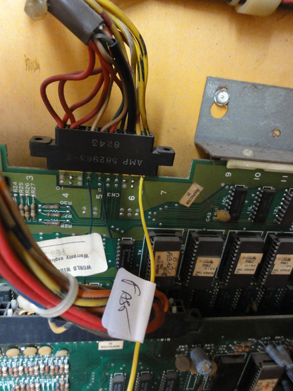
OK, the basic check. Let's plug the game. On this pin, I'm supposed to have 12V ...
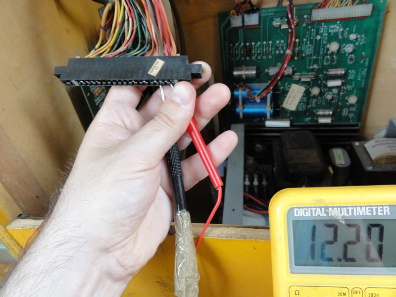
...looks good.
Now, on this one I should have +5V ...
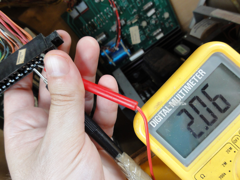
2,06 ?! Not good! Every pin I'm supposed to have +5V, I have only +2V

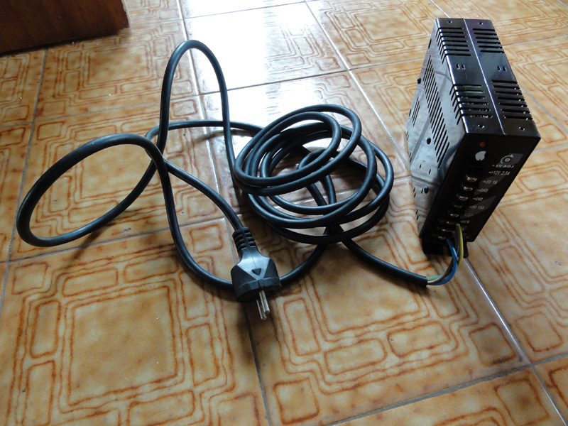
The "Medium Power Supply" board should provide correctly the +5V everywhere, but not anymore now... I do not have a rebuild kit here, so let's help it to provide the +5V with an other power supply. Fortunately, I always have one, ready for such operation


Ok, so far I only need two wires : one for 5V and one for the ground, see
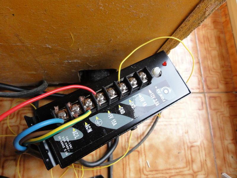
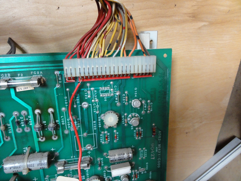
The red one provides the +5V. Because I do not want the cut the wires at this place, I simply hang the wire, it will be fine for just a test :
The yellow one is the ground :
Power on... something on the screen

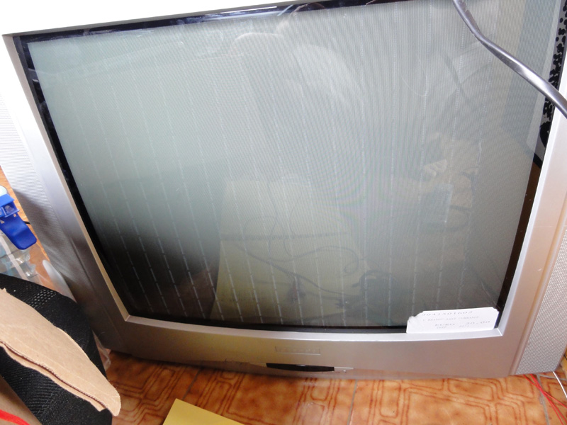
After few seconds... I recognize the game... and I recognize that 'one color' display... I know for sure that my *VIDEO* custom adapter Burger Time > Scart is working... I just need to add the RGB switching signal

Let's add it ( +5V on Scart pin 16) ... and ...
...
...
... THIS IS IT
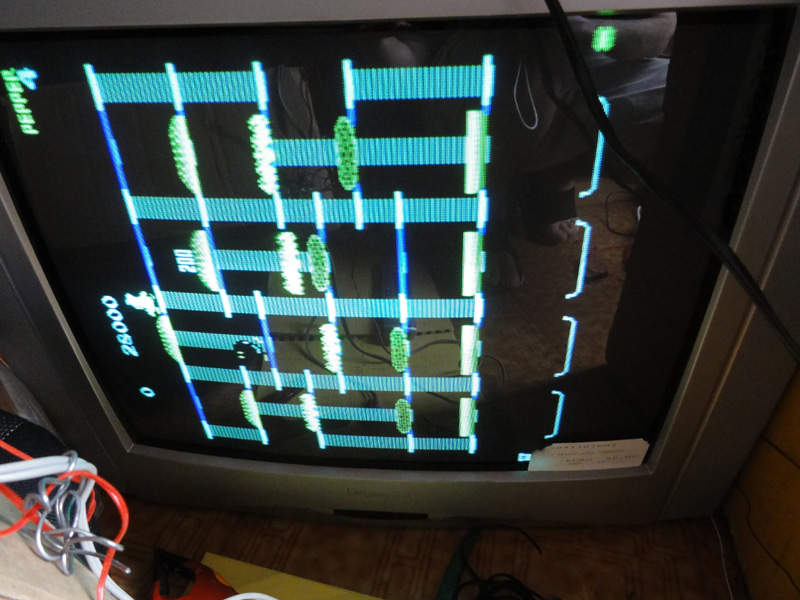
Well... almost, just a small mistake between the thee colors wires (RGB)... Let check that....
... and ...
... and ...
THIS IS IT NOW
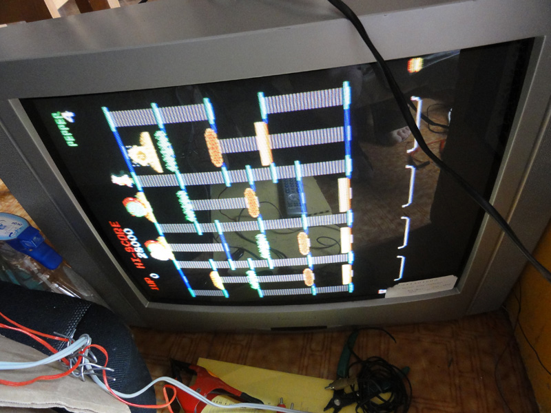
OK, I know the only problem (so far, let's be prudent
) is ...the "Midway Medium Power Supply". Once I'll have the rebuild kit, this issue will be fixed and I won't need that *temporary* external power supply
Hey, because I was very happy to see the board ALIVE, I've done a real time
video ... enjoy