1
Arcade Lifestyle / Baby Pong - A Half Size Pong Replica
« on: June 11, 2017, 06:36:40 AM »
A week ago I decided I was going to knock up a 1/2 size Pong cab.
The purpose of the build was to check the dimensions of the plans and work out any issues if they arise with the artwork and finishing of the cab in preparation for a full size build.
At that stage I wasn't aware of Etienne's build thread on here though I vaguely recall seeing it a couple of years ago before joining the forum.
The panels will be 9mm MDF for the fromt and 9mm plywood for the sides, adhesive vinyl was used for the woodgrain.
https://www.bunnings.com.au/boyle-1-5m-x-45cm-natural-dark-wood-self-adhesive-film_p1661110
The control panel was printed it onto gloss photo paper at home.
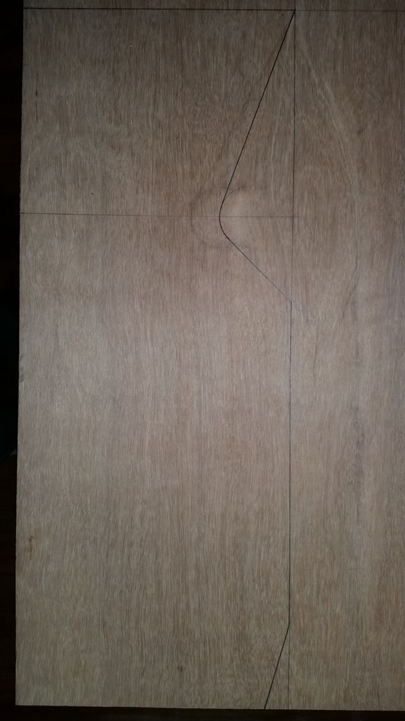
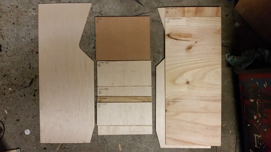
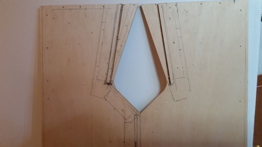
I've learnt that it's easier the make a template out of 18mm marine ply for the irregular shapes and flush trim each panel with the template using a router.
A complete side can be cut and shaped in a mater of seconds as opposed to hand cutting the profiles with a jigsaw (which never cuts perpendicular) and sanding into shape.
A fair amount of time and attention to detail is required for fabricating the templates but the amount of time saved when cutting multiple panels is definitely worth the effort.
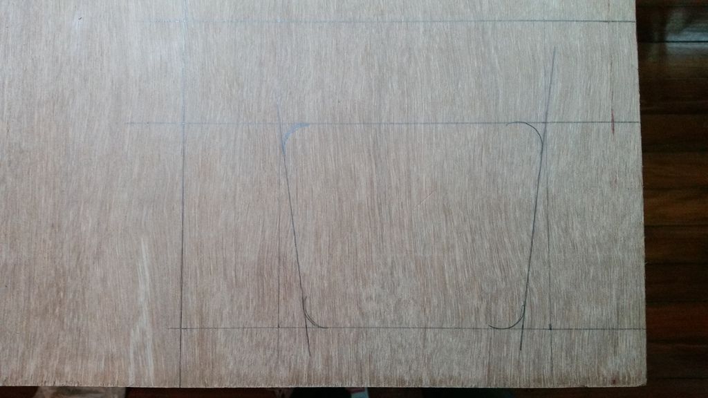
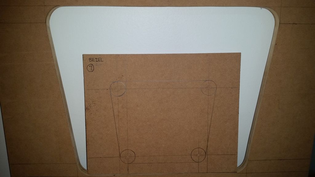
The same was done for the bezel cutout.
Here's a short video of the flush cutting being done.
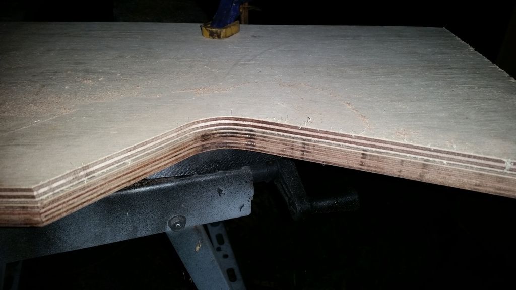
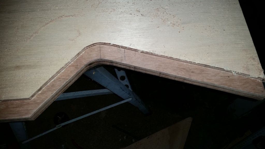
The blank panel was cut 3mm oversize.
I use the template to draw an image over the panel and rough cut the profile with a jigsaw.
The roughed out panel is laid over the top of the template and the bit is set so that he cutting edge is 1 or 2 mm longer than the panel you're cutting.
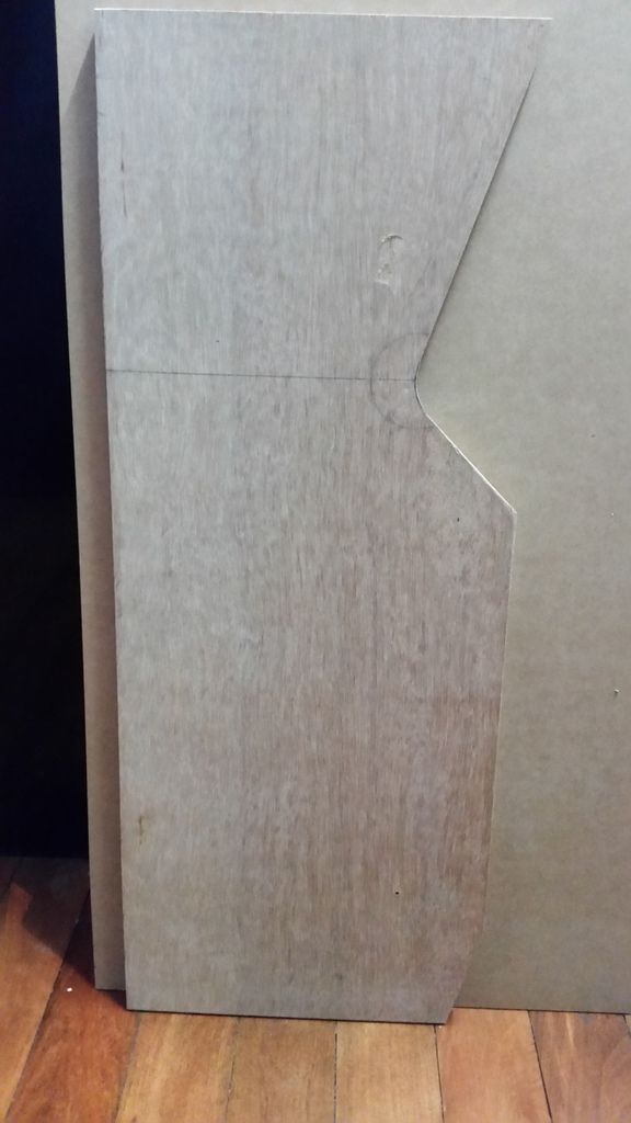
I square the bottom and back edges together with the template then clamp them together, I do a first trim to reduce the 3mm down by about 50%.
I then do a final pass in one straight run if possible.
https://www.youtube.com/watch?v=AB5VaO7ek-0
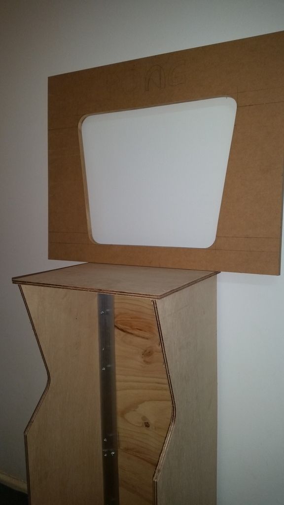
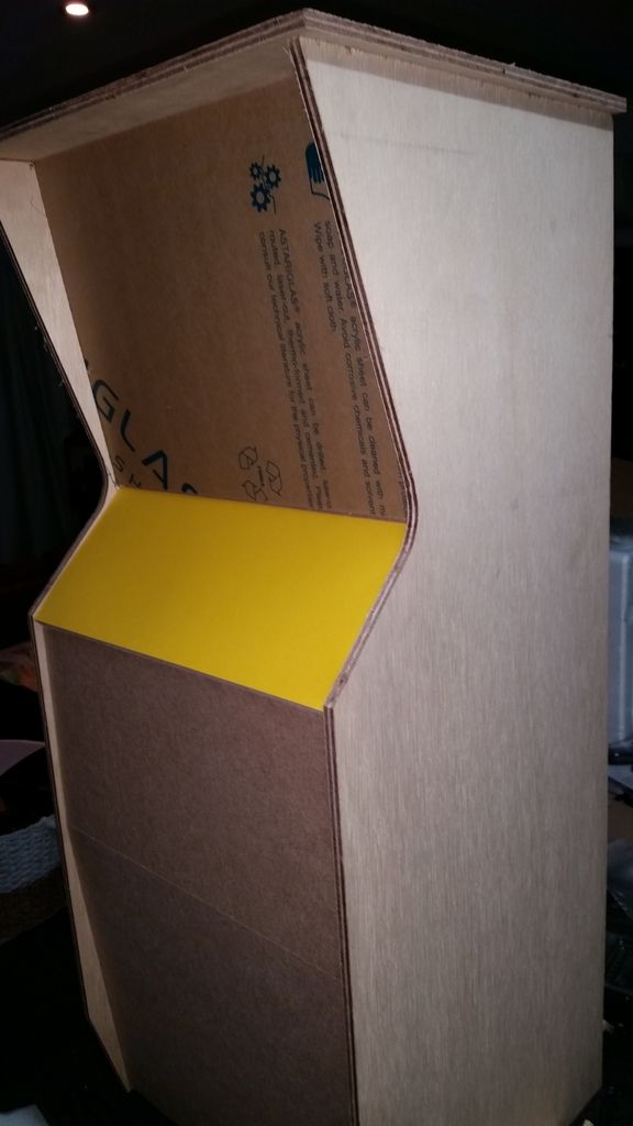
Baby Pong is born...
The cabinet initial assembly is complete.
The bezel still needs to be routed out and and the control panel will be redone in 12mm MDF.
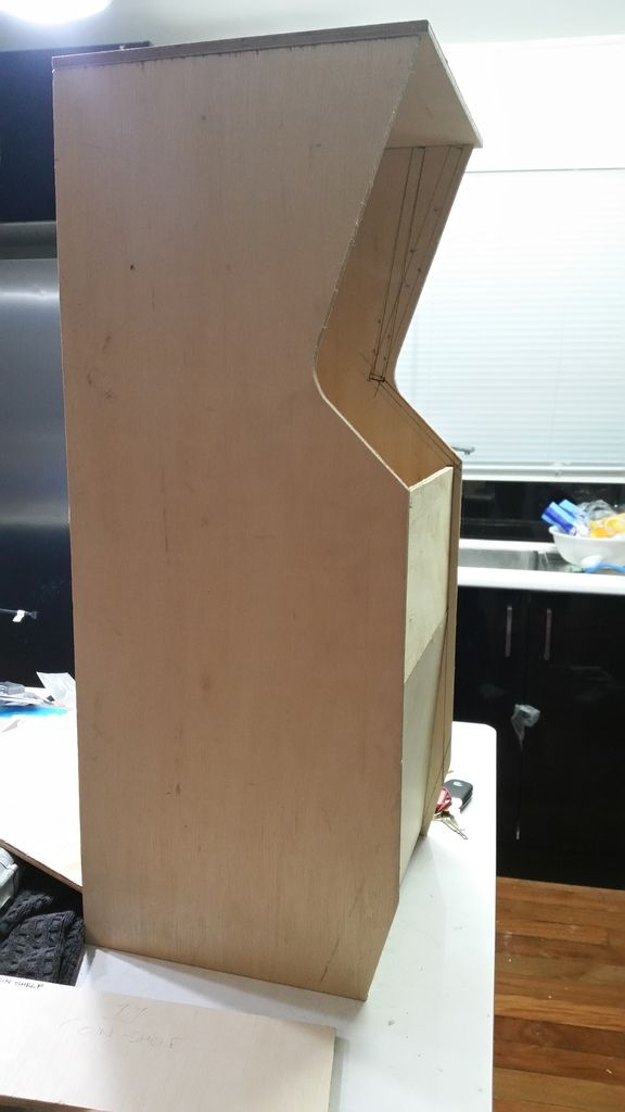
I also made a bezel template for a full size cab
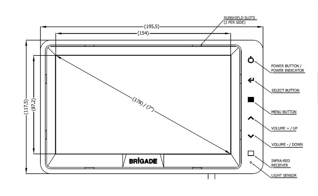
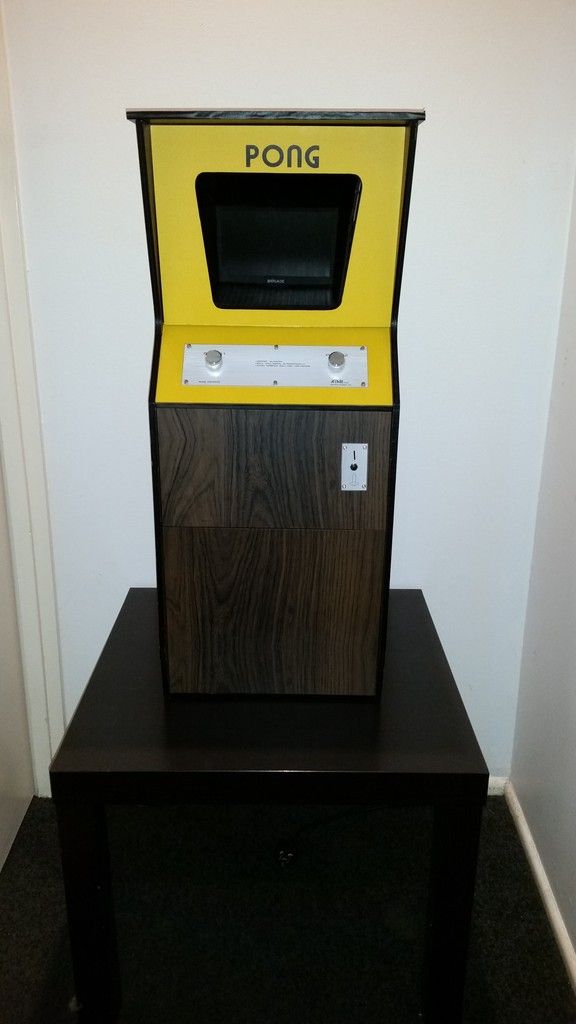
The monitor is a 16:9, 7" Reversing Camera Monitor.
https://www.youtube.com/watch?v=MhWRzKrPokw
I picked up the perspex screen and control panel overlay for $5.
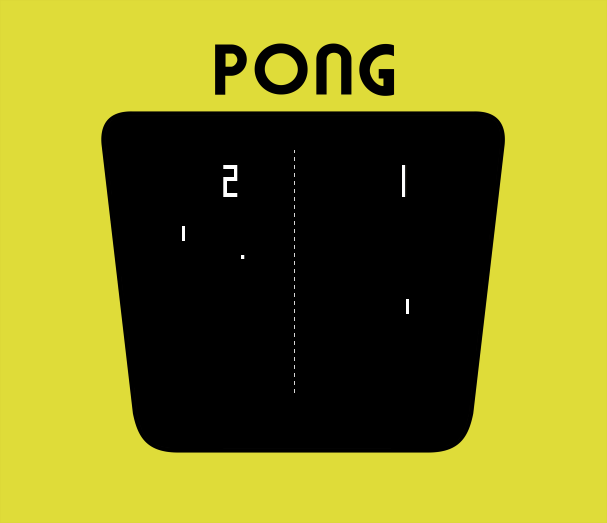
This cab will have yellow card stock with PONG printed on it which sits behind the perspex.
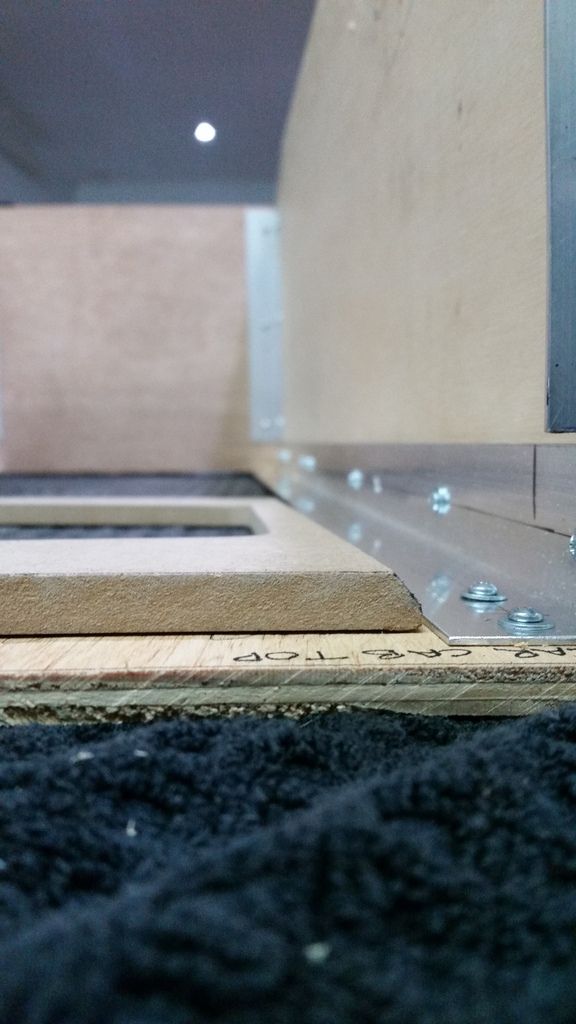
The perspex screen for the bezel has been cut 6mm wider than the panels and will be rebated into the sides.
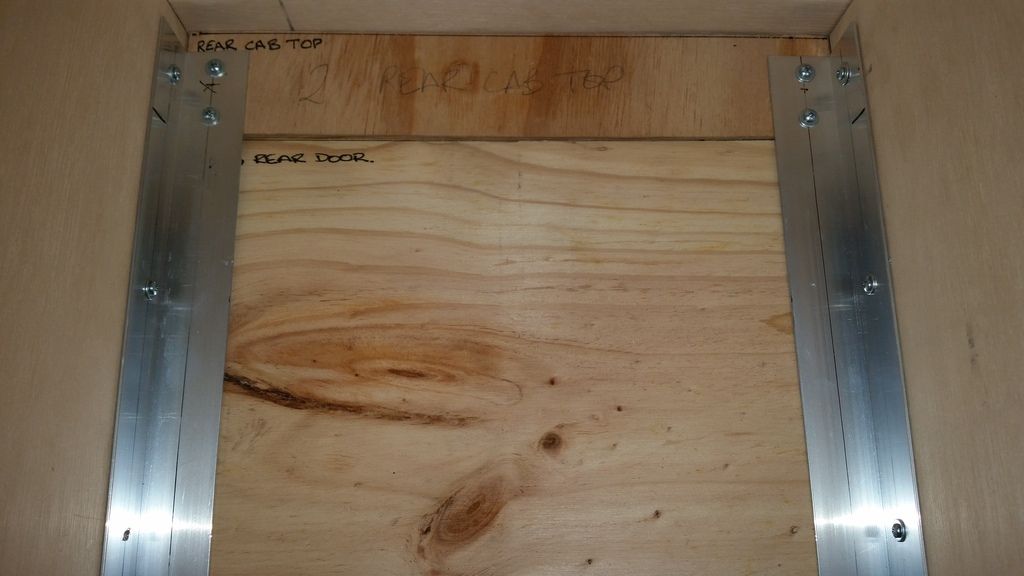
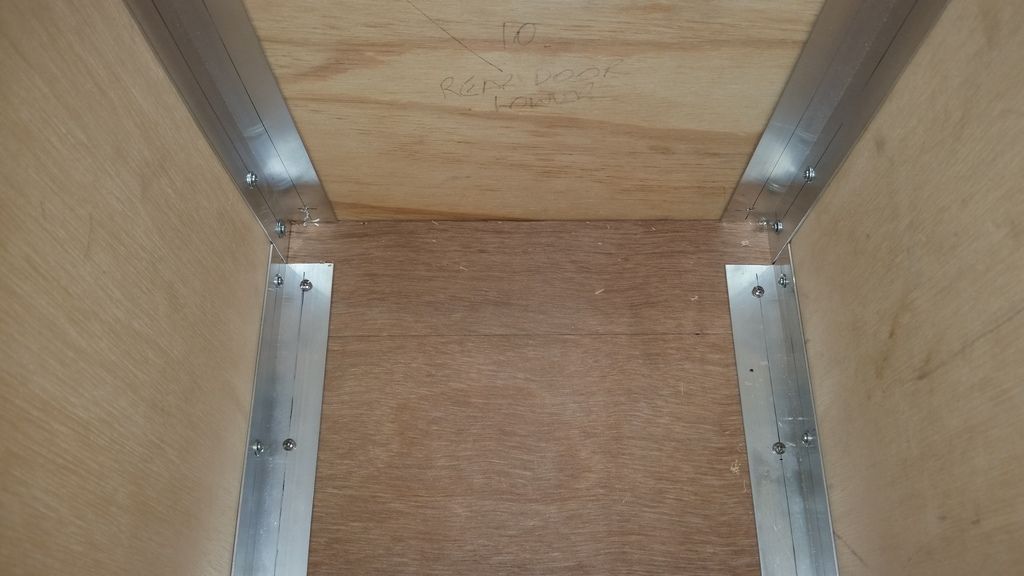
All the front panels are now cut I also cut a second set at the same time.
I tested them in place and the dims are spot on.
There's nothing holding the front panels in place in the image below apart from the interference fit.
The bezel has been copied from the template.
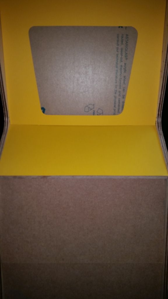
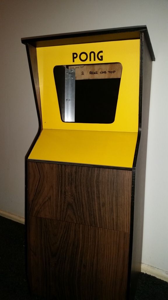
We have colour...
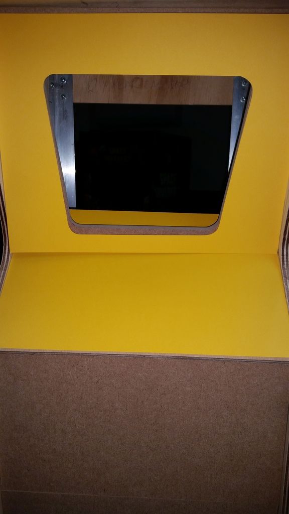
The first shot is with the flash and the second is without.
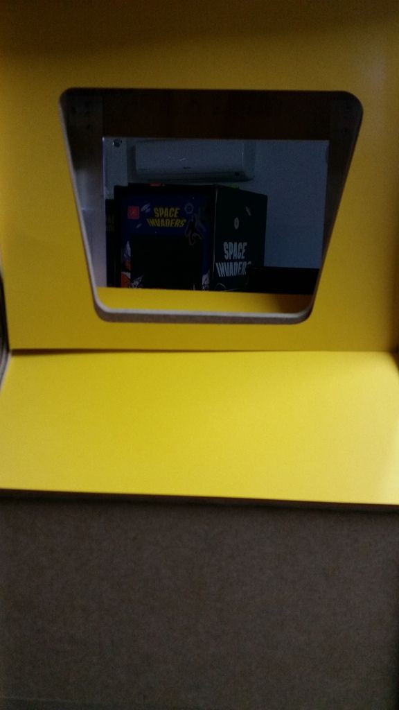
It was the closest I could find from Officeworks, it's just sitting in place but I'm happy with the colour.
The internal width of the cabinet (297mm) is exactly the same width as a piece of A3 card stock.
The 4.5mm clear perspex will lay over the top.
I just need to get 'PONG" printed portrait and dead centre on the other piece I bought before I cut it.
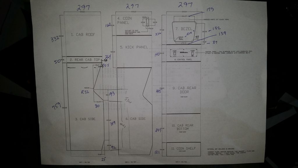
Here's the current build plans I'm working from.
These are a work in progress and are missing some information.
I'm constantly adjusting dims as the build progresses.
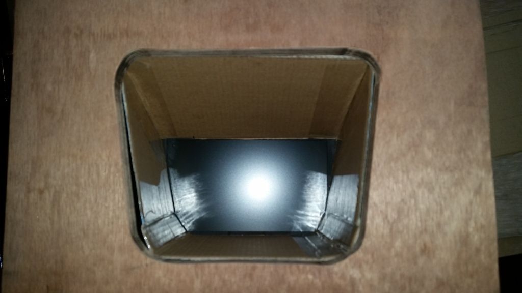
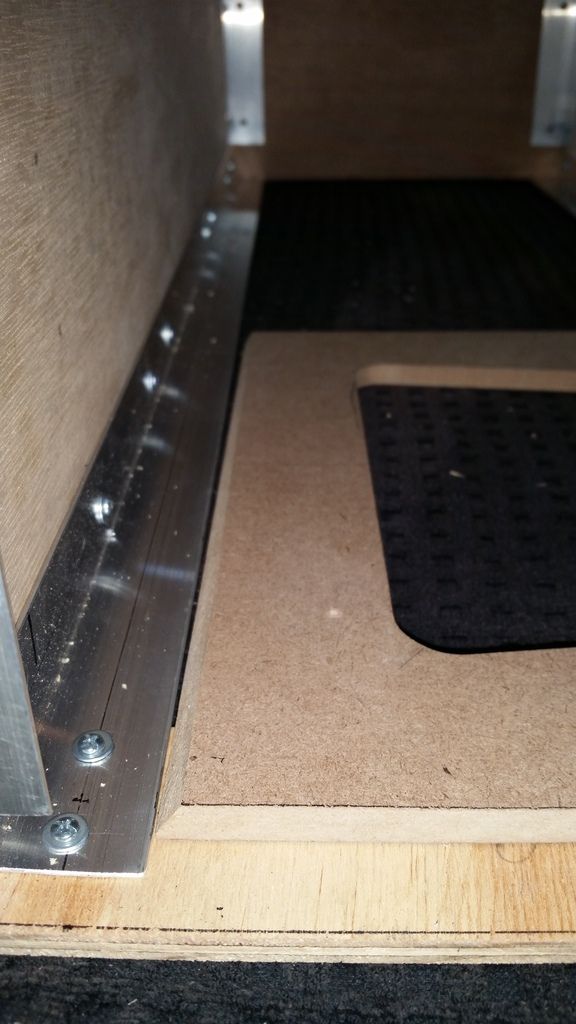
The cardboard piece for between the bezel and monitor has been roughly shaped and will be redone in thick matt black card stock once I'm happy with the final position.
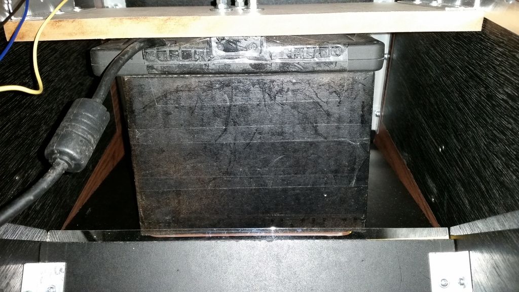
The LCD will sit 125mm back from the bezel.
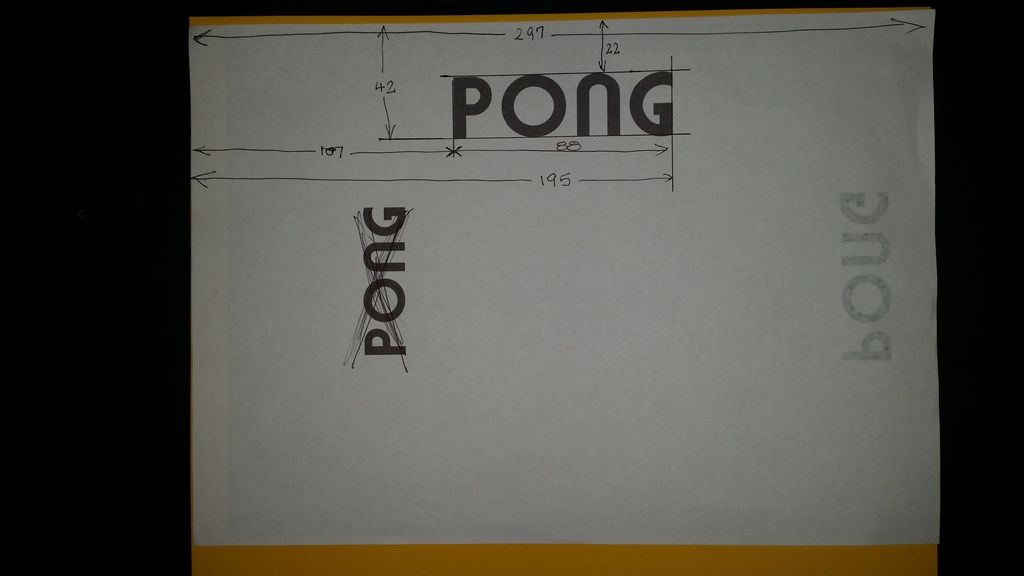
It's time to get to work on the 'PONG' marquee.
At first glance it's only 4 letters but it does need to look correct and be positioned in the right place to be printed straight from the file onto a piece of yellow card at Officeworks without tweaking.
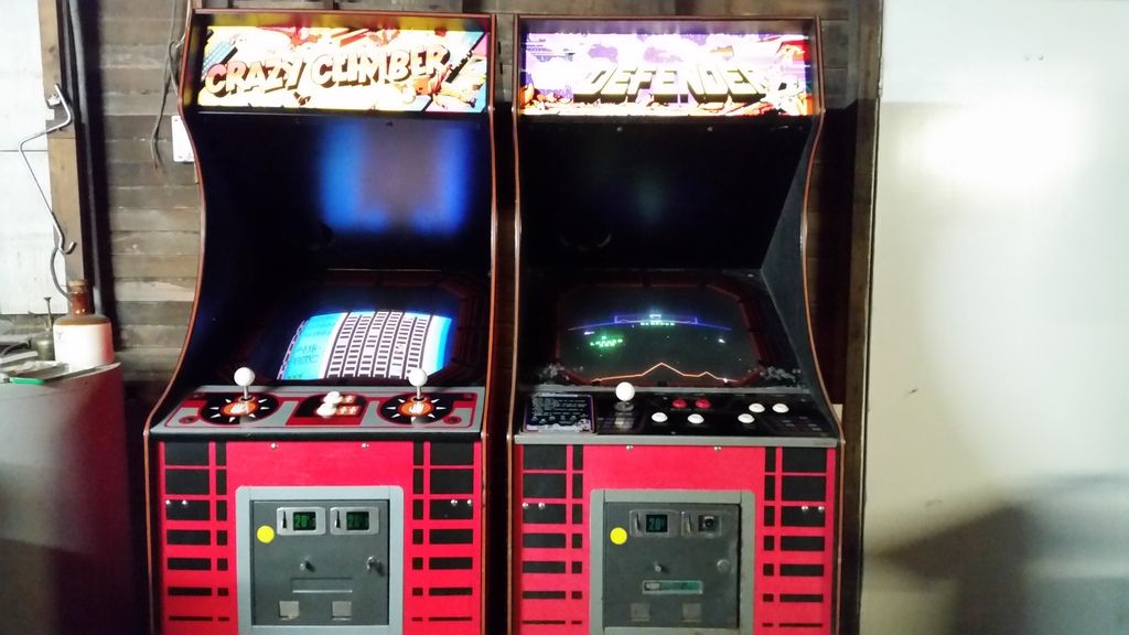
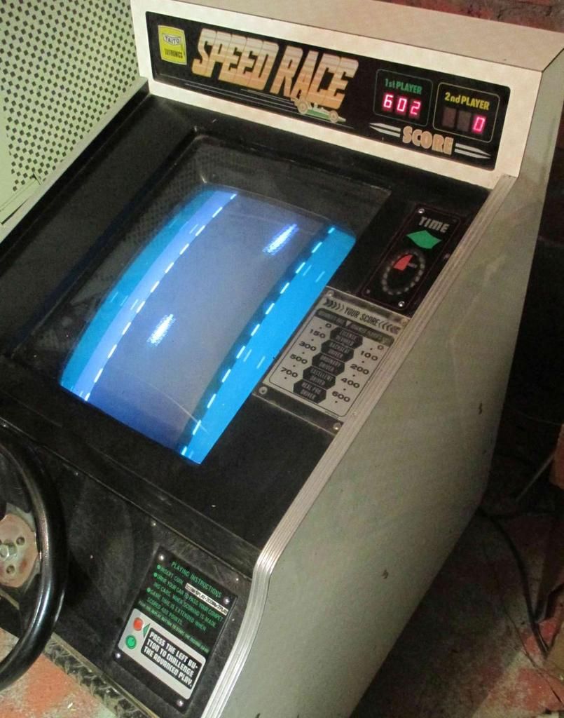
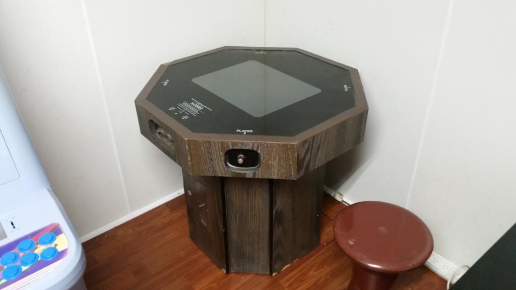
Here are some reference images I started off with.
Basically I just needed PONG positioned in the middle and a small distance down from the top of an A3 sheet in portrait.
A member on another forum helped me out as I'm terrible at Adobe Illustrator.

I'd also like to get this done in an EPS cut file as well so I can get one laser cut in yellow perspex as well...
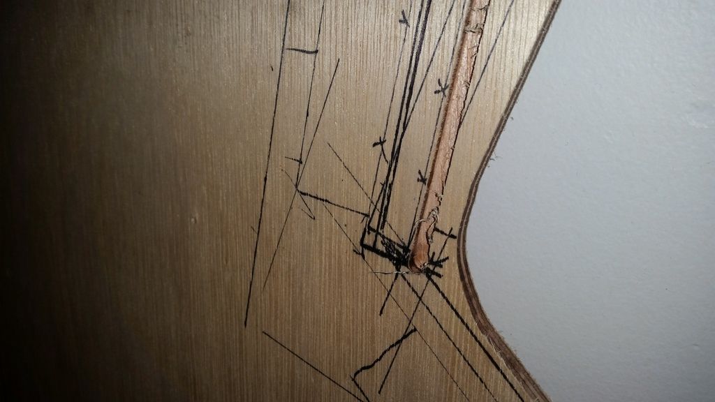
The bezel needed a back angle at the rear edges, top and bottom.
I set the table saw to 35 degrees and ran each side through a few times until the blade was just short of the bottom edge.
It will all be hidden by the yellow card and perspex sheet so a perfect knife point edge isn't needed.
The cab is now stripped back down again so I can route the rebate for the bezel glass (perspex).
All panels are now cut and pre screwed.
I'll reassemble it again and make final adjustments so everything is a tight fir.
The router bit is slightly larger than 4.5mm ,
I'll lay the woodgrain vinyl over the panel and slice it down the centre line of the rebate, that should take up a little more of the gap and give it a softer edge than the wood to sit against. As long as it doesn't rattle it should be okay.
The cab is back together, it takes an hour to put the flatpack together.
The perspex screen was slotted in during assembly and the the rebate depth was perfect.
The next big challenge is getting the 1/2 size control panel artwork done.
I first need to find the drive with the artwork file from Etienne.
I found the artwork file for the bezel, the width is 23.7 inches or 601mm, close enough for a full size cab.
It was used to create a blank PONG image positioned so that it will print in the centre of an A3 sheet and the correct distance down.
I also worked out the 1/2 size dimensions for the marquee.
For a perectly centred text 107 should be 109.5mm, that will be fixed before printing.
I believe everything else is correct.
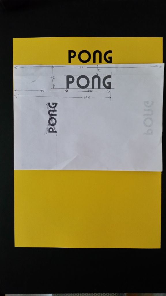
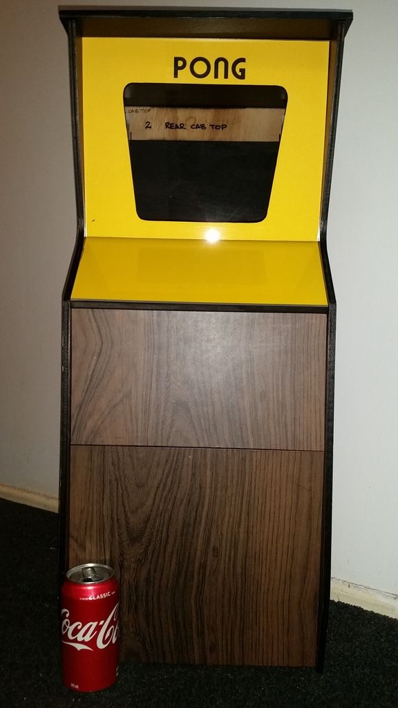
The next day I got it printed onto A3 Yellow Card Stock like the image below at Officeworks .
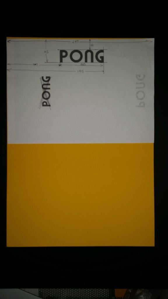
I got two sheets printed at Officeworks for a total of $2 and done in 5 mins.
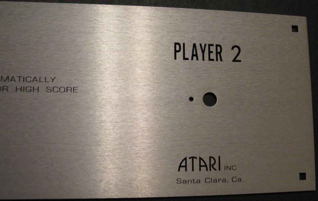
I had a play around in MS Paint and spliced together the two partial scans I had for the control panel.
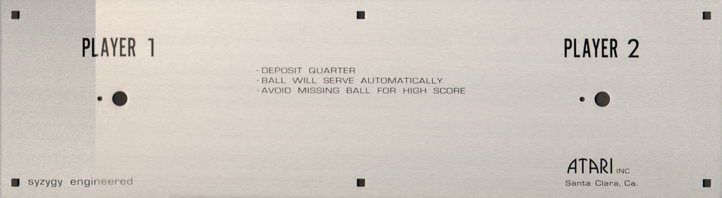
That's the limit of my artwork production skills.
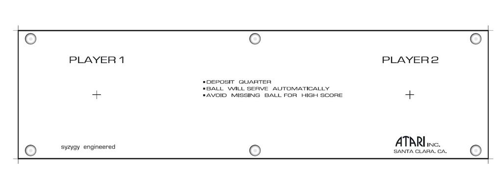
Just as I has done that I finally got a hold of the CPO atrwork file that I couldn't find.
All the panels are prepped and painted and wrapped with self adhesive vinyl.
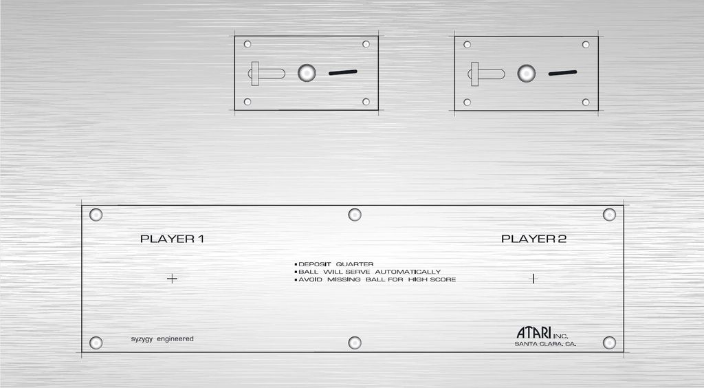
I worked out how to lay the text over some Brushed Metal texture in Ai and I'm happy with how it looks.
Almost done...
I placed a Coke can in front for perspective.
A test piece has been printed off for checking the CPO size, looks good to me...
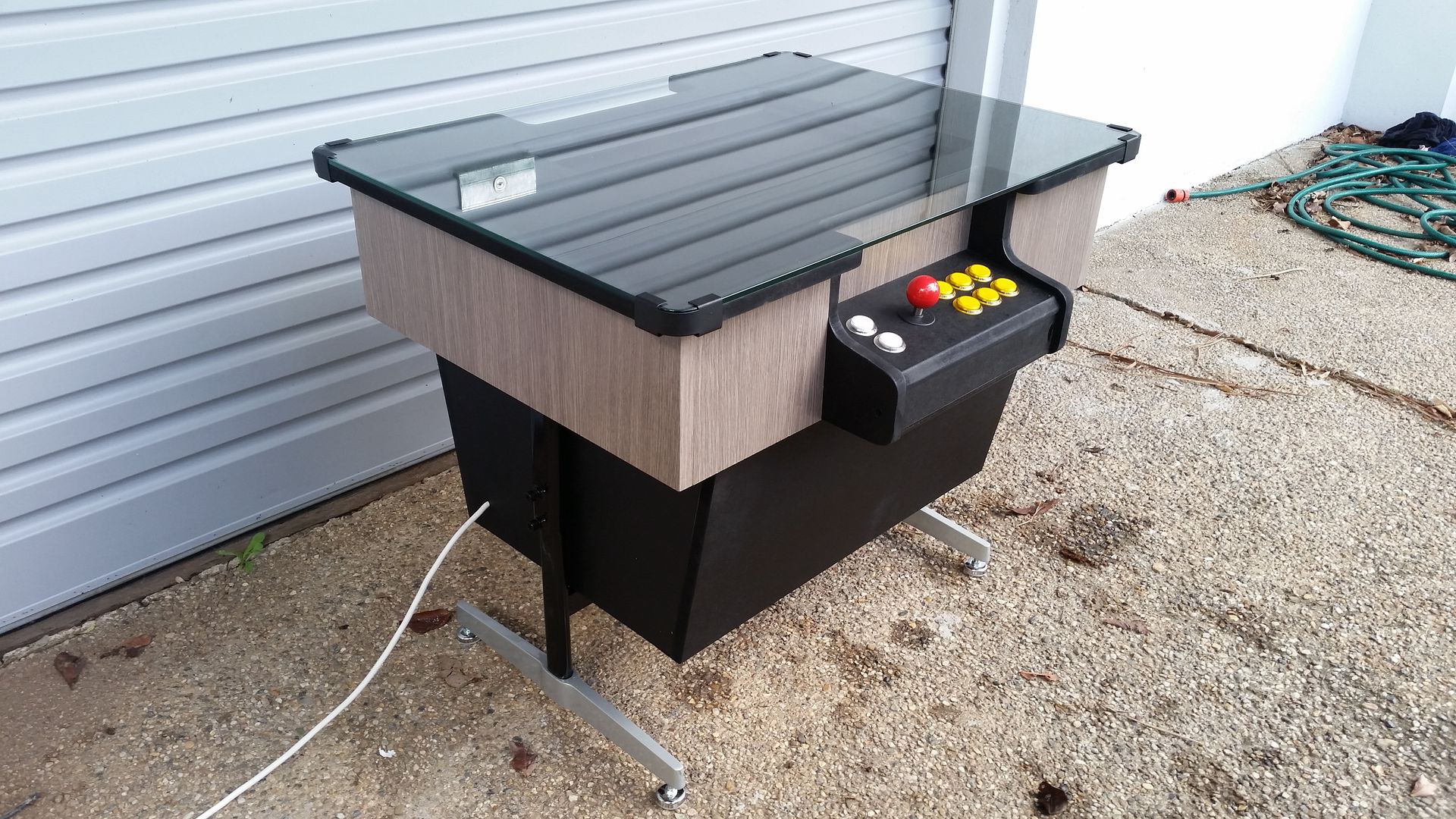
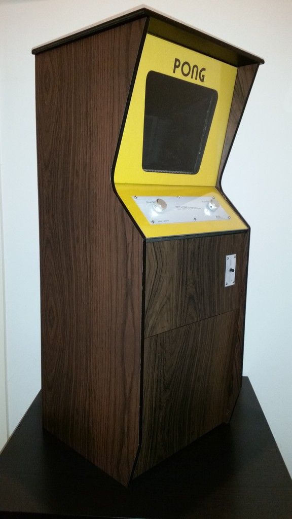
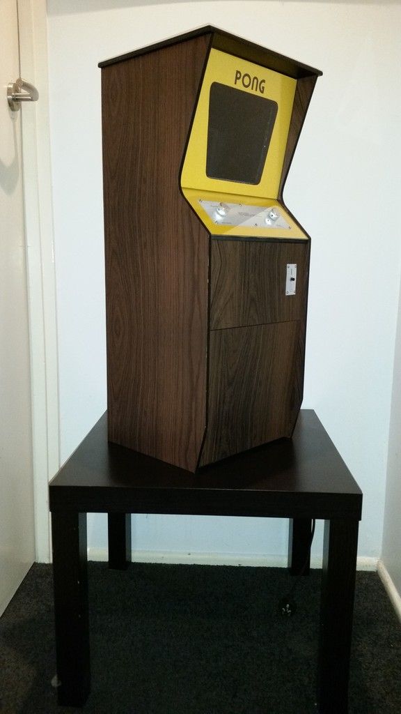
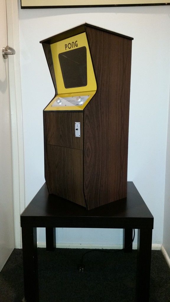
Baby Pong Build is complete.
It's taken just over a week to build but over 60 hours worth of work went into it.
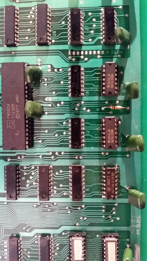
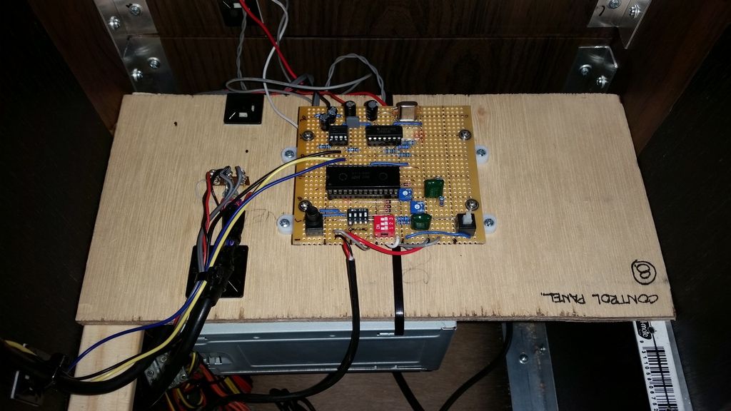
I'm really proud of this little cab, everything has been scratch built including the game board.
A lot of lessons were learnt for when I build a full size cab.
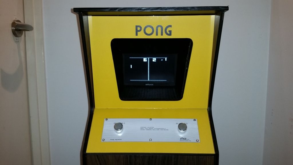
There's still a few little things I need to do but it's now complete and working.
The purpose of the build was to check the dimensions of the plans and work out any issues if they arise with the artwork and finishing of the cab in preparation for a full size build.
At that stage I wasn't aware of Etienne's build thread on here though I vaguely recall seeing it a couple of years ago before joining the forum.
The panels will be 9mm MDF for the fromt and 9mm plywood for the sides, adhesive vinyl was used for the woodgrain.
https://www.bunnings.com.au/boyle-1-5m-x-45cm-natural-dark-wood-self-adhesive-film_p1661110
The control panel was printed it onto gloss photo paper at home.
I've learnt that it's easier the make a template out of 18mm marine ply for the irregular shapes and flush trim each panel with the template using a router.
A complete side can be cut and shaped in a mater of seconds as opposed to hand cutting the profiles with a jigsaw (which never cuts perpendicular) and sanding into shape.
A fair amount of time and attention to detail is required for fabricating the templates but the amount of time saved when cutting multiple panels is definitely worth the effort.
The same was done for the bezel cutout.


Here's a short video of the flush cutting being done.
The blank panel was cut 3mm oversize.
I use the template to draw an image over the panel and rough cut the profile with a jigsaw.
The roughed out panel is laid over the top of the template and the bit is set so that he cutting edge is 1 or 2 mm longer than the panel you're cutting.
I square the bottom and back edges together with the template then clamp them together, I do a first trim to reduce the 3mm down by about 50%.
I then do a final pass in one straight run if possible.
https://www.youtube.com/watch?v=AB5VaO7ek-0


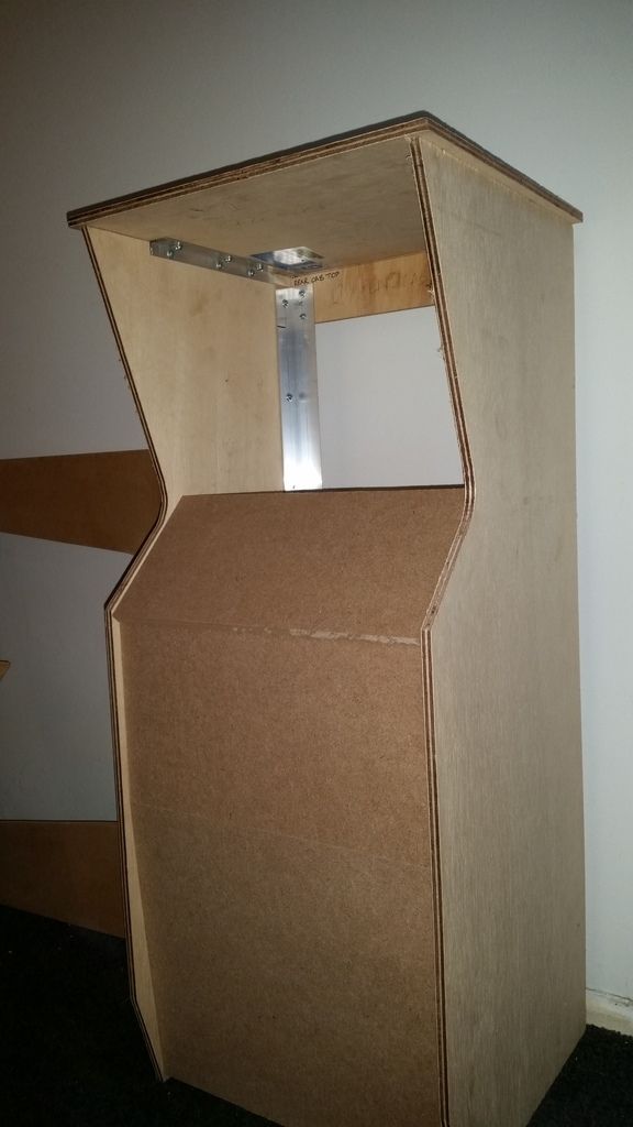
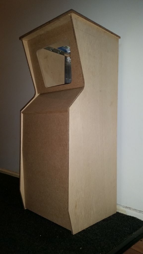
Baby Pong is born...
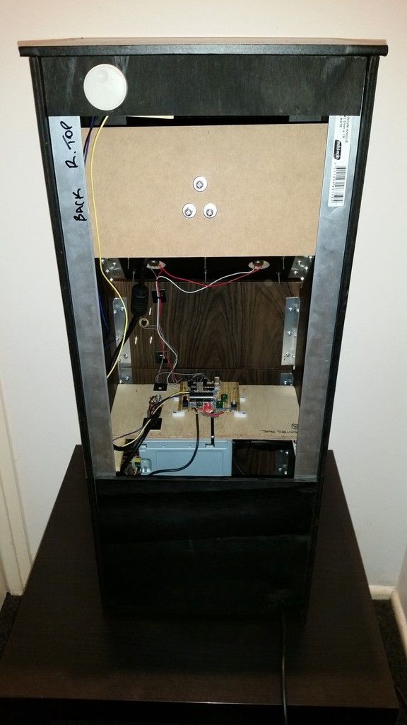
The cabinet initial assembly is complete.
The bezel still needs to be routed out and and the control panel will be redone in 12mm MDF.


I also made a bezel template for a full size cab


The monitor is a 16:9, 7" Reversing Camera Monitor.

https://www.youtube.com/watch?v=MhWRzKrPokw

I picked up the perspex screen and control panel overlay for $5.
This cab will have yellow card stock with PONG printed on it which sits behind the perspex.
The perspex screen for the bezel has been cut 6mm wider than the panels and will be rebated into the sides.
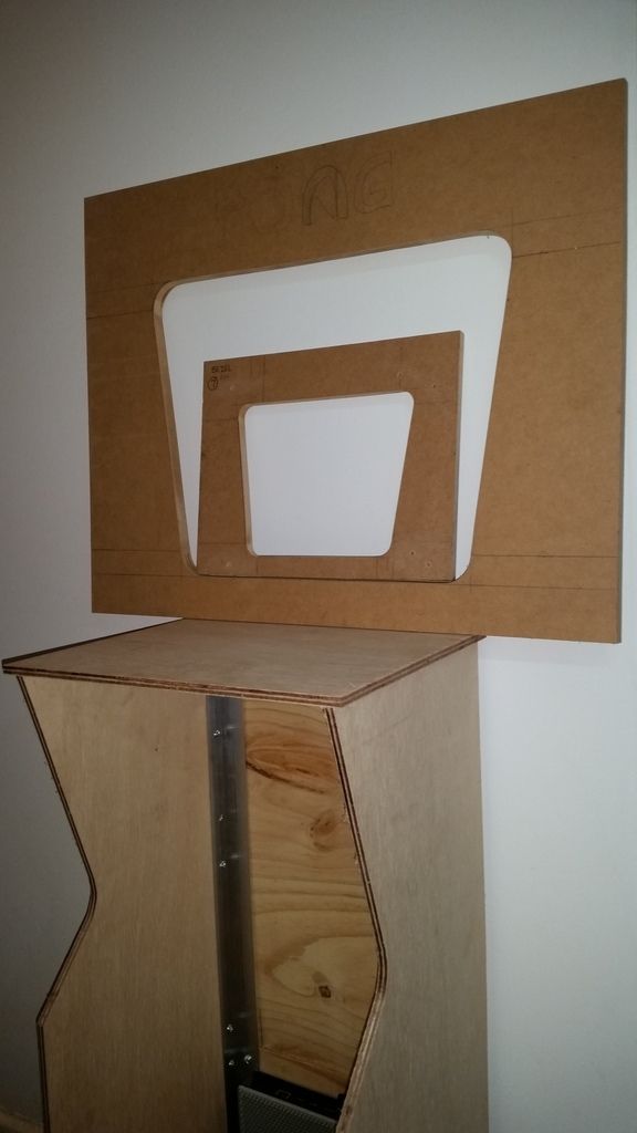
All the front panels are now cut I also cut a second set at the same time.
I tested them in place and the dims are spot on.
There's nothing holding the front panels in place in the image below apart from the interference fit.

The bezel has been copied from the template.

We have colour...

The first shot is with the flash and the second is without.

It was the closest I could find from Officeworks, it's just sitting in place but I'm happy with the colour.
The internal width of the cabinet (297mm) is exactly the same width as a piece of A3 card stock.
The 4.5mm clear perspex will lay over the top.
I just need to get 'PONG" printed portrait and dead centre on the other piece I bought before I cut it.
Here's the current build plans I'm working from.
These are a work in progress and are missing some information.
I'm constantly adjusting dims as the build progresses.

The cardboard piece for between the bezel and monitor has been roughly shaped and will be redone in thick matt black card stock once I'm happy with the final position.
The LCD will sit 125mm back from the bezel.

It's time to get to work on the 'PONG' marquee.
At first glance it's only 4 letters but it does need to look correct and be positioned in the right place to be printed straight from the file onto a piece of yellow card at Officeworks without tweaking.
Here are some reference images I started off with.
Basically I just needed PONG positioned in the middle and a small distance down from the top of an A3 sheet in portrait.
A member on another forum helped me out as I'm terrible at Adobe Illustrator.

I'd also like to get this done in an EPS cut file as well so I can get one laser cut in yellow perspex as well...

The bezel needed a back angle at the rear edges, top and bottom.
I set the table saw to 35 degrees and ran each side through a few times until the blade was just short of the bottom edge.
It will all be hidden by the yellow card and perspex sheet so a perfect knife point edge isn't needed.

The cab is now stripped back down again so I can route the rebate for the bezel glass (perspex).

All panels are now cut and pre screwed.
I'll reassemble it again and make final adjustments so everything is a tight fir.
The router bit is slightly larger than 4.5mm ,
I'll lay the woodgrain vinyl over the panel and slice it down the centre line of the rebate, that should take up a little more of the gap and give it a softer edge than the wood to sit against. As long as it doesn't rattle it should be okay.


The cab is back together, it takes an hour to put the flatpack together.
The perspex screen was slotted in during assembly and the the rebate depth was perfect.


The next big challenge is getting the 1/2 size control panel artwork done.
I first need to find the drive with the artwork file from Etienne.


I found the artwork file for the bezel, the width is 23.7 inches or 601mm, close enough for a full size cab.
It was used to create a blank PONG image positioned so that it will print in the centre of an A3 sheet and the correct distance down.
I also worked out the 1/2 size dimensions for the marquee.
For a perectly centred text 107 should be 109.5mm, that will be fixed before printing.
I believe everything else is correct.

The next day I got it printed onto A3 Yellow Card Stock like the image below at Officeworks .

I got two sheets printed at Officeworks for a total of $2 and done in 5 mins.

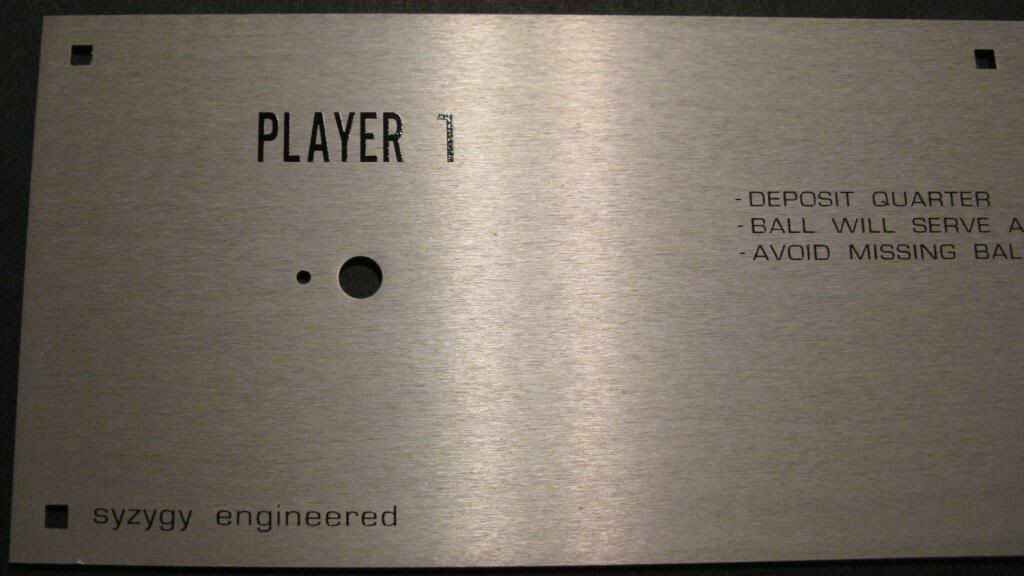
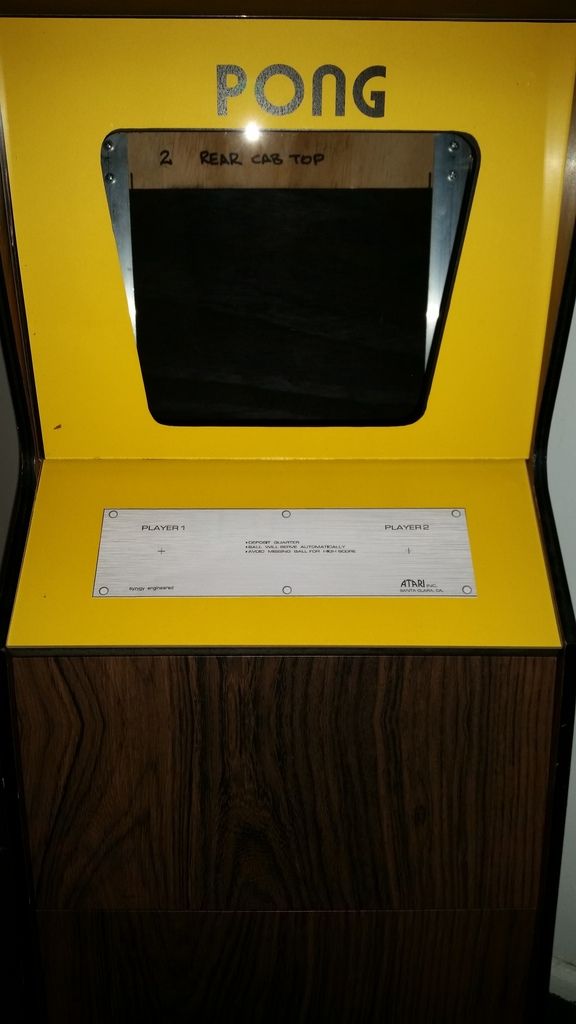
I had a play around in MS Paint and spliced together the two partial scans I had for the control panel.

That's the limit of my artwork production skills.
Just as I has done that I finally got a hold of the CPO atrwork file that I couldn't find.

All the panels are prepped and painted and wrapped with self adhesive vinyl.
I worked out how to lay the text over some Brushed Metal texture in Ai and I'm happy with how it looks.

Almost done...

I placed a Coke can in front for perspective.

A test piece has been printed off for checking the CPO size, looks good to me...

Baby Pong Build is complete.
It's taken just over a week to build but over 60 hours worth of work went into it.
I'm really proud of this little cab, everything has been scratch built including the game board.
A lot of lessons were learnt for when I build a full size cab.

There's still a few little things I need to do but it's now complete and working.